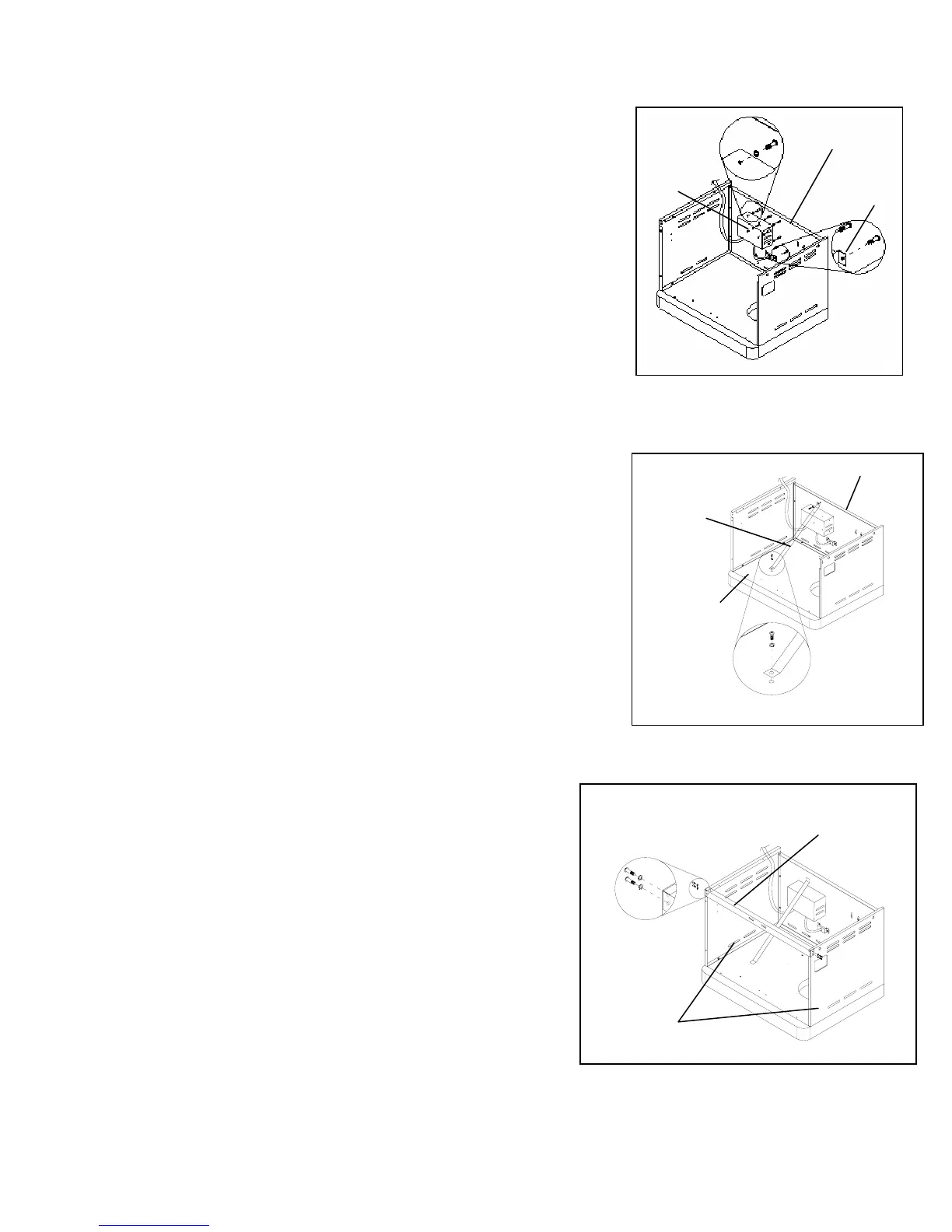
Fig. 5
4. Transformer Box Assembly
B
Align the holes of the transformer box (A) with the holes on the
back panel (B). Attach the transformer (A) to the back panel (B)
using six 5/32-in. x 10-mm truss head screws from pack A and
six 5/32-in. locking washers from pack B as shown in fig. 5.
A
C
The power cord bracket (C) connects to the rear cart panel
using two 5/32-in. x 10-mm truss head screws from pack A and
two 5/32-in. locking washers from pack B as shown in fig.5.
Fig. 6
5. Spare Liquid Propane Tank Barrier Bar Assembly
Attach the barrier bar (A) to the bottom panel (B) and back
panel (C) using two 5/32-in. x 10-mm truss head screws from
pack A and two 5/32-in. locking washers from pack B as shown
in fig. 6.
6. Cart Frame Assembly
Remove the cart frame from the carton (A). Attach the
cart frame (A) to the side panels (B) using four 1/4-in. x
15-mm truss head screws from pack C and four 1/4-in.
locking washers from pack D as shown in fig. 7.
Note: Hinge bracket slot will need to be facing upwards.
Fig. 7
A
B
C
B
10


 To Next Page