OPERATION
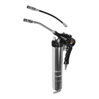
OPERATING THE GREASE GUN
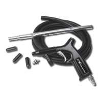
Note: If your application requires the Flexible Hose (11), attach it to the
Bent Spout (7).
WARNING: Before every use, prime the Grease Gun by operating the
Gun (see below) until grease ows from the tip. If it does not prime
properly, follow the directions above for venting trapped air.
1. Attach the Grease Gun to the air source hose following the directions
on page four. Set the air compressor to 30 - 100 PSI.
2. Squeeze the Trigger (3) to begin the ow of grease.
3. Release the Trigger (3) to stop the ow of Grease.
4. Disconnect from the air source hose before relling the Grease Gun.
Turn off the air compressor.
WARNING: The Grease Gun may still have air pressure after discon-
nected from the air source. Point the Grease Gun into a suitable recep-
tacle and re it until all of the air is expended.
GREASE LOADING INSTRUCTIONS
Grease can be loaded into the Grease Gun by: loading with a ller
pump, using suction lling, or loading with a cartridge.
WARNING: Disconnect the Grease Gun from the air supply before lling.
Loading A Grease Cartridge
1. Remove the Container Tube (8) from the top of the Housing Cap (6).
2. Pull back on the Plunger Handle (10) until it is fully extended. Lock it
into place with the Catch Plate (12).
automatic oiler system, before operation, add a few drops
of Pneumatic Tool Oil to the airline connection. Add a few
drops more after each hour of continual use.
2. To check your air system, set the air pressure on your
compressor to 90 PSI. Do not exceed the testing air pres-
sure of 90 PSI.
3. Check the air connection for leaks. After test is complete,
disconnect from the air supply until grease is loaded into
the Air Grease Gun.
1 295001-1 Housing 1
2 295002-1 O-Ring 1
3 295003-1 O-Ring 3
4 295004-1 Valve Stem 1
5 295005-1 O-Ring 2
6 295006-1 Valve 1
7 295007-1 Spring 1
8 295008-1 Valve Plug 1
9 295009-1 Trigger 1
10 295010-1 Trigger Pin 1
11 295011-1 Screw 1
12 295012-1 Washer 1
13 295013-1 Rubber Cup 1
14 295014-1 Washer 1
15 295015-1 Spring Seat 1
16 295016-1 Piston Seat 1
17 295017-1 Lever 1
18 295018-1 Tower Spring 1
19 295019-1 Connection 1
20 395047-1 Washer 1
21 395048-1 Container Tube 1
22 295022-1 Screw 1
23 295023-1 Steel Ball 2
24 295024-1 Tower Spring 1
25 295025-1 Tube 1
26 295026-1 Screw 1
27 295027-1 O-Ring 2
28 295028-1 Spring 1
29 295029-1 Rubber Seat 1
30 295030-1 Bushing 1
31 295031-1 Arc Board 4
32 295032-1 Retainer 1
33 295033-1 Screw 1
34 295034-1 Spring 1
35 295035-1 Valve 1
36 295036-1 Spring 1
37 295037-1 Valve Stem 1
38 295038-1 Vacuum Valve 1
39 295039-1 Screw 4
40 295040-1 Cover 1
41 297007-1 Air Inlet 1
42 295042-1 Washer 1
43 395040-1 Steel Ball 1
# Part # Description Quantity
REPLACEMENT PARTS LIST