4. Carefully, reassemble the Container
Tube (8) to the top on the Housing
Cap (6). Press the Catch Plate (12)
and release the Plunger Handle
(10). Press the Plunger Handle (10)
in as far as it will go.
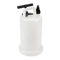
Loading with a Filler Pump
(not included)
1. Slowly, pull back and fully extend
the Plunger Handle (10). Lock it into
place with the Catch Plate (12).
2. Insert the Filler Plug on the end of
the hose of the Filler Pump (not
included) into the Filler Plug (13).
3. Follow the instructions provided in
the Filler Pump manual (not includ-
ed) to operate the Filler Pump until
the Container Tube (8) is full.
OPERATION OPERATION OPERATION
FIG. E
3. Remove the caps/lids from both ends of the cartridge (not included).
Insert the cartridge into the Container Tube (8) in the orientation indi-
cated on the cartridge, making sure that it is in as far as possible.
4. Reassemble the Container Tube (8) to the top on the Housing Cap
(6). Press the Catch Plate (12) and release the Plunger Handle (10).
Press the Plunger Handle (10) in as far as it will go.
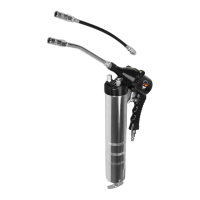
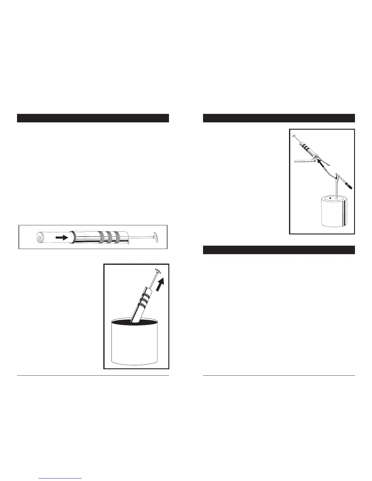
Suction Filling
1. Remove the Container Tube (8) from the top of the Housing Cap (6).
2. Submerge the open end of the Container Tube (8) approximately 2
inches into the grease container (not included).
3. Slowly, pull back and fully extend the Plunger Handle (10) to draw
grease upward into the Container Tube (8). When the Plunger Handle
(10) is fully extended, lock it into place with the Catch Plate (12).
FIG. D
OPERATION OPERATION OPERATION
Clean air of correct air pressure is recommended for the power supply
for this tool. A maximum of 90 PSI at the tool is recommended for most
air tools of this class. Check specications section for recommended
pressure. (Depending on length of air hose and other circumstances, air
pressure at compressor may need to be increased to 100 PSI to ensure
90 PSI at the tool.)
Water in the air hose and compressor tank contributes to reduced per-
formance and damage of the air tool. Drain the air tank and lters before
each use and as necessary to keep the air supply dry.
Hose length over 25’ causes loss in line pressure. Increase hose I.D. or
increase compressor pressure to compensate for the pressure loss. Use
an in-line pressure regulator with gauge if air inlet pressure is critical.
AIR SOURCE
FIG. F
4. Disconnect the Grease Gun from the
Filler Pump (not included).
5. Press the Catch Plate (12) and
release the Plunger Handle (10).
Press the Plunger Handle (10) in as
far as it will go.