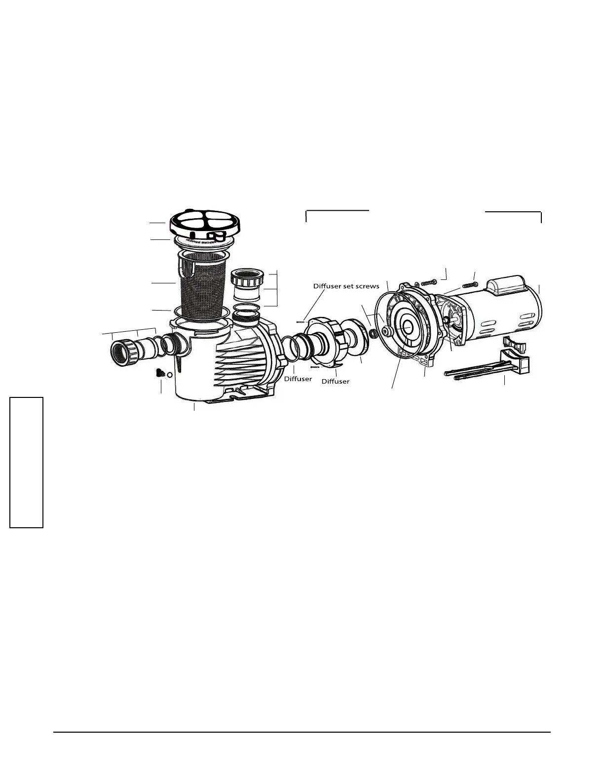
Clamp Ring
Lid
Basket
Lid o-ring
Nut
Tailpiece
Tailpiece
o-ring
Drain plug
& o-ring
Volute
Union
Assembly
o-ring
Impeller
Bracket
Motor Base
Motor
1 1/8”
Hex Bolts (6)
7/8”
Hex Bolts (4)
Bracket o-ring
Mechanical
Seal
Union
Assembly
Bracket Bore
o-ring
Slinger
Pump Disassembly
All moving parts are located in the rear sub-assembly of this pump.
Tools required:
1. 3/32 inch Allen wrench
2. 7/16 inch open end wrench
3. 9/16 inch open end wrench
4. Small and large athead screwdrivers
5. #3 Phillips screw driver
Disassembly and repair of the motor sub-assembly can be made as follows:
2. Close all necessary valves on inlet and discharge lines and drain the pump by removing both drain
plugs.
3. Loosen and remove the six (6) 1-1/8” hex bolts that hold the volute and the bracket together.
4. Pull the rear sub-assembly away from the volute. The volute may remain attached to the plumbing.
5. Loosen and remove the two (2) diuser set screws that hold the diuser to the bracket.
6. Remove the set screw from the impeller eye, if present. To remove, hold the impeller stationary and
turn the set screw clockwise to loosen (screw is left-hand threaded).
7. Hold the motor shaft stationary by removing the cap on the opposite end of the motor and inserting a
screw driver in the slot or use a wrench on the at spot on the motor shaft depending on the motor
design and unscrew the impeller by turning it counter clockwise.
8. Loosen and remove the four (4) 7/8” hex-bolts that hold the bracket to the motor face.
9. To remove the shaft seal, place the bracket face down on a at surface and press out the
carbon/spring seal from the back side. Never pry it out from the front. Carefully remove the ceramic
seal from the back of the impeller hub by carefully prying up with a small athead screw driver.
10.
Clean the bracket, seal bore housing and the motor shaft as necessary. Remove slinger if replacing
bearings.
8
1. Disconnect the pump from the power source by unplugging or turn o at the circuit breaker.
Rear Sub-assembly
MAINTENANCE
 Loading...