Typical example
(1) Exhaust inlet from back pressure valve
(2) Selective Catalytic Reduction (SCR)
system
(3) Exhaust out
(4) Ammonia sensor (if equipped)
(5) Nitrogen Oxide (NOx) sensor
(6) Diesel Exhaust Fluid (DEF) injector
(7) Diesel Exhaust Fluid (DEF) supply line
(8) Diesel Exhaust Fluid (DEF) pump and
dosing control unit
(9) Coolant supply from engine line
(10) Coolant diverter valve
(11) Diesel Exhaust Fluid (DEF) tank
(12) Coolant supply connector
(13) Suction connector
(14) Backflow connector
(15) Coolant return connector
(16) DEF suction line
(17) Electronic Control Module (ECM)
Note: Illustration 24 is a schematic for illustrative
purposes only. Ensure that the diesel exhaust fluid
pump is installed to the application in the correct
orientation. Refer to Disassembly and Assembly,
“Diesel Exhaust Fluid Pump - Remove and Install” for
the correct procedure.
The Diesel Exhaust Fluid (DEF) Dosing Control
System consists of the following components.
• Pump Electronics Unit (PEU)
• DEF injector
• DEF header
• Coolant diverter valve
• DEF System Heated Lines
Pump Electronics Unit (PEU)
The Pump Electronics Tank Unit (PEU) consists of
the following components.
• DEF pump
• Dosing Control Unit (DCU)
The Dosing Control Unit (DCU) is mounted on the
DEF pump assembly.
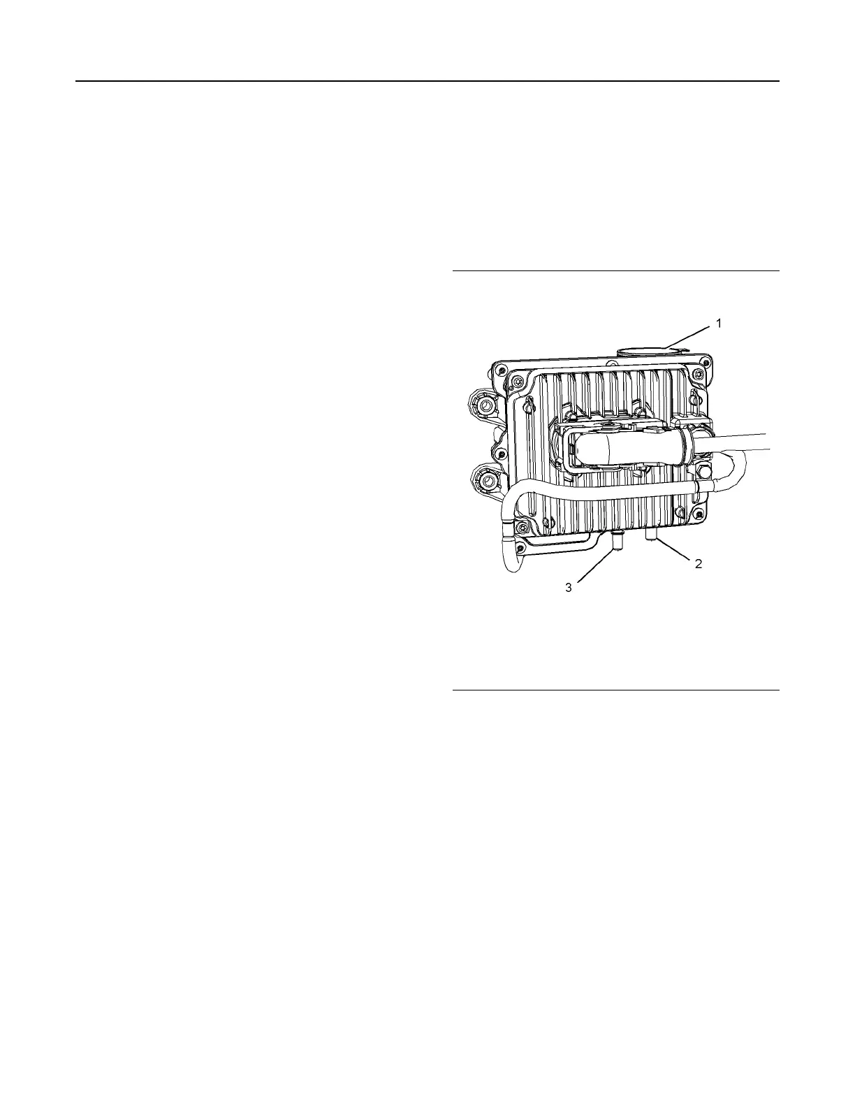
DEF Pump
Illustration 25 g03708834
Typical example
(1) DEF filter
(2) Inlet
(3) Outlet
The pump supplies filtered DEF fluid to the DEF
injector. The pump consists of inlet port (2) which is
the suction side of the pump. The pump then
pressurizes the fluid up to 550 kPa (80 psi) and
supplies the fluid though outlet port (3). There is a
fixed orifice within the DEF injector that governs the
return flow from the DEF injector to the tank. This
return flow will stabilize the temperature in the DEF
injector when the DEF injector is exposed to the hot
gases from the exhaust.
UENR4490-01 31
Engine Operation
This document has been printed from SPI2. NOT FOR RESALE





 To Next Page