3. Install Tooling (B) into the hole (X) in the cylinder
block. Use Tooling (B) in order to locate the
crankshaft in the correct position.
Note: Do not use excessive force to install Tooling
(B). Do not use Tooling (B) to hold the crankshaft
during repairs.
4. Check the rocker arms for an engine valve lash.
There should be no engine valve lash.
Illustration 86 g02333215
Typical example
One electronic unit injector is not shown for clarity.
5. If there is an engine valve lash at any position the
engine valve lash may be caused by a normal
leakdown of the hydraulic lifter. Push the affected
rocker arm (1) against the pushrod. The rocker
arm (1) should rotate as the pushrod is pushed up
by the recovery of the hydraulic lifter. Once all
motion has ceased test again for an engine valve
lash. There should be no engine valve lash.
6. Remove Tooling (B) from the crankshaft. Use
Tooling (A) to rotate the crankshaft in a clockwise
direction. The crankshaft should be rotated 360
degrees. Install Tooling (B) to the crankshaft.
7. Check the rocker arms for an engine valve lash.
There should be no engine valve lash.
8. If there is an engine valve lash at any position the
engine valve lash may be caused by a normal
leakdown of the hydraulic lifter. Push the affected
rocker arm (1) against the pushrod. Monitor the
rocker arm (1) for movement. The rocker arm (1)
should rotate as the pushrod is pushed up by the
recovery of the hydraulic lifter. Once all motion has
ceased test again for an engine valve lash. There
should be no engine valve lash.
9. If an engine valve lash is found in any position,
examine the valve mechanism components for
excessive wear or damage. This includes the
hydraulic lifters.
i04215789
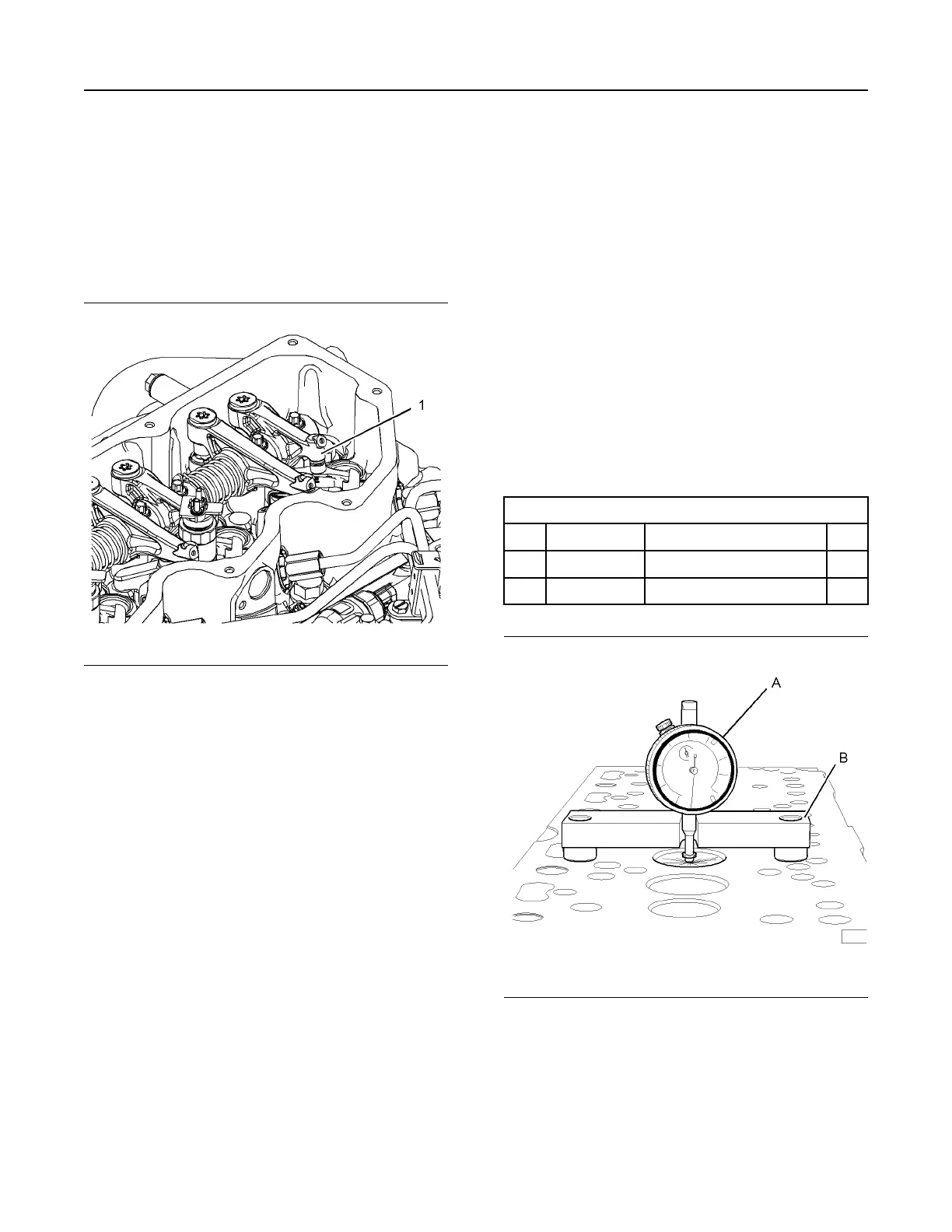
Valve Depth - Inspect
Table 7
Required Tools
Tool Part Number
Part Description Qty
A
21825617
Dial gauge
1
B
21825496
Dial gauge holder
1
Illustration 87 g01201916
Typical example
UENR4490-01 97
Air Inlet and Exhaust System
This document has been printed from SPI2. NOT FOR RESALE
 Loading...


