cooling system or the engine. Refer the service
manual in order to check for leakage. If the
exhaust gas cooler (NRS) does leak, the
exhaust gas cooler (NRS) should be replaced.
2. Follow steps 2.a to 2.i in order to test the gas side
of the exhaust gas cooler (NRS).
a. Plug the gas inlet (5) of the exhaust gas cooler
(NRS) (3).
b. Plug the gas outlet port (1) with tube and
pressure regulator assembly.
c. Make sure that the air pressure regulator is
closed and connect compressed air to the
pressure regulator.
d. Use a suitable pressure gauge in order to apply
an air pressure of 250 kPa (36 psi) to the
exhaust gas cooler (NRS).
e. While the exhaust gas cooler (NRS) is still
pressurized, submerge the cooler in water that
is at ambient temperature.
f. Allow the exhaust gas cooler (NRS) to settle in
order for the air that is trapped to escape.
g. Observe the exhaust gas cooler (NRS) for air
bubbles that indicate a leak. If air bubbles are
seen within 3 minutes, this indicates a leak with
the exhaust gas cooler (NRS). Note the location
or the origin of the leak. Record this information.
h. If no bubbles are detected after 3 minutes, the
exhaust gas cooler (NRS) is reusable.
i. Remove the exhaust gas cooler (NRS) from the
water. If the exhaust gas cooler (NRS) does not
leak, the problem may be elsewhere in the
cooling system or the engine. Refer the service
manual in order to check for leakage. If the
exhaust gas cooler (NRS) does leak, the
exhaust gas cooler (NRS) should be replaced.
i04027325
Compression - Test
The cylinder compression test should only be used in
order to compare the cylinders of an engine. If one or
more cylinders vary by more than 350 kPa (51
psi),
the cylinder and related components may need to be
repaired.
A compression test should not be the only method
which is used to determine the condition of an
engine. Other tests should also be conducted in
order to determine if the adjustment or the
replacement of components is required.
Before the performance of the compression test,
make sure that the following conditions exist:
• The battery is in good condition.
• The battery is fully charged.
• The starting motor operates correctly.
• The valve lash is correct.
• All glow plugs are removed.
• The ECM is powered.
• The fuel pressure sensor is connected.
• The suction control valve is connected.
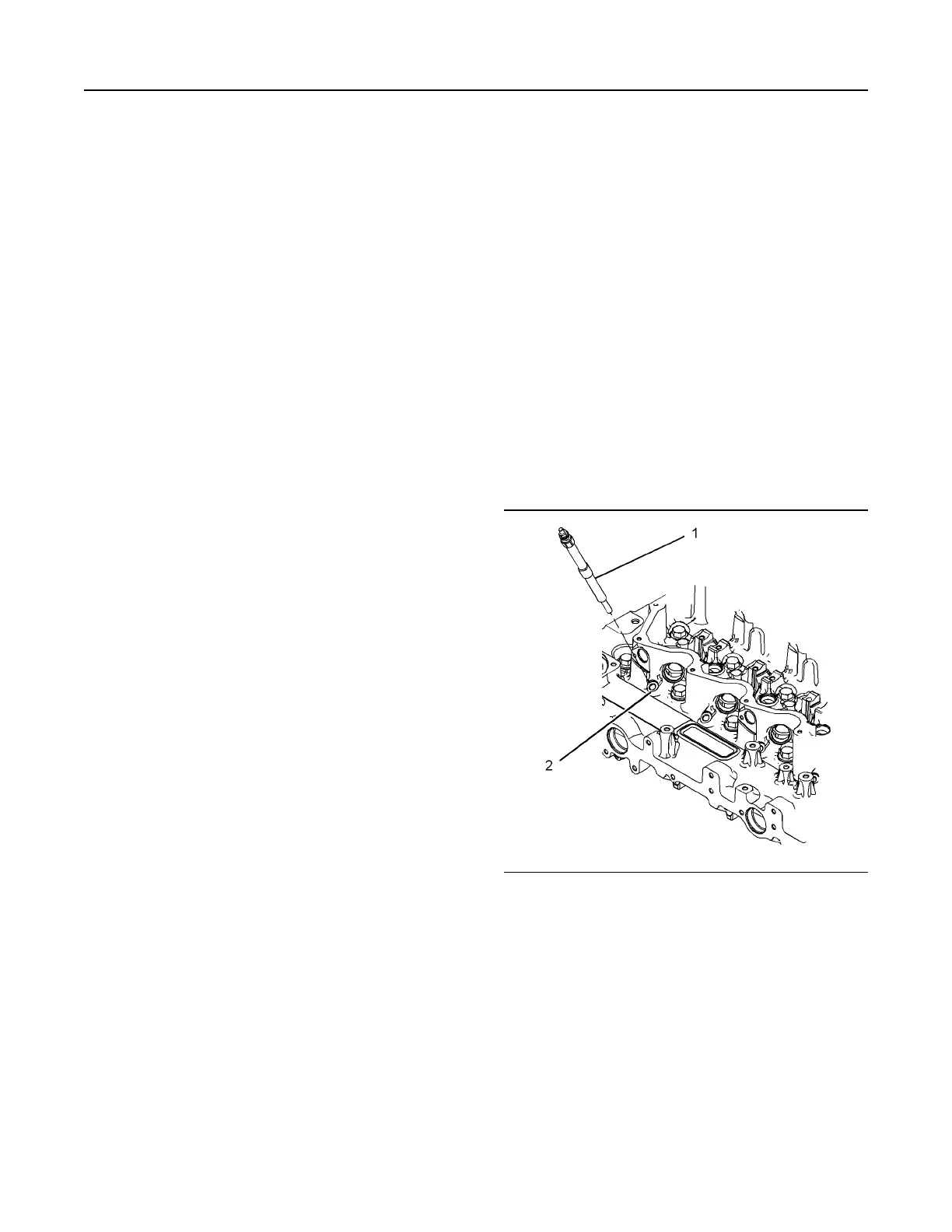
Illustration 83 g01925436
Typical example
1. Remove the glow plug (1). Refer to Disassembly
and Assembly, “Glow Plugs - Remove and Install”
for the correct procedure.
2. Install a suitable gauge for measuring the cylinder
compression in the hole for the glow plug.
3. Remove the fuse for the glow plugs.
4. Operate the starting motor in order to turn the
engine. Record the maximum pressure which is
indicated on the compression gauge.
5. Repeat steps 2 and 4 for all cylinders.
UENR4490-01 95
Air Inlet and Exhaust System
This document has been printed from SPI2. NOT FOR RESALE
 Loading...


