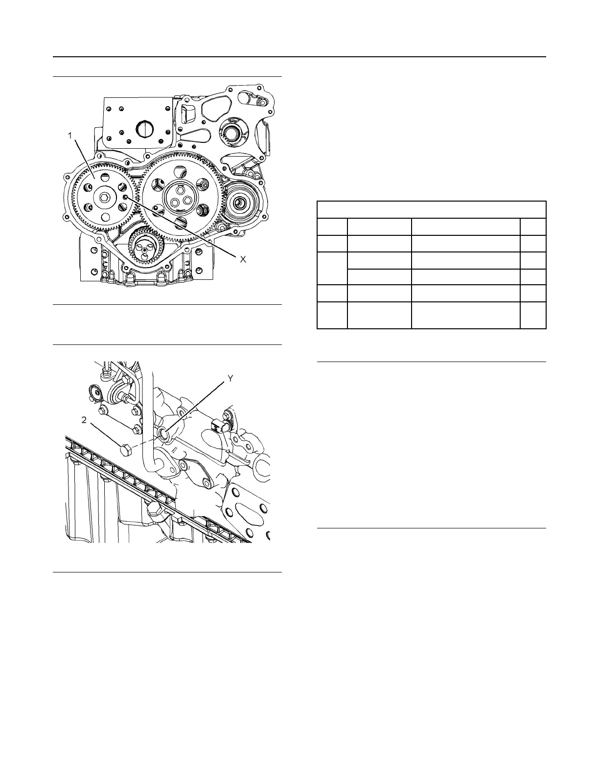
Illustration 71 g01907734
Typical example
Illustration 72 g01907735
Typical example
2. Use Tooling (A) in order to rotate the crankshaft
until the Hole (X) in the camshaft gear (1) aligns
with the hole in the front housing. Refer to
illustration 71 . Remove the plug (2) from the
cylinder block. Install Tooling (C) into the Hole (Y)
in the cylinder block. Use Tooling (C) in order to
lock the crankshaft in the correct position.
Note: Do not use excessive force to install Tooling
(C). Do not use Tooling (C) to hold the crankshaft
during repairs.
3. Install Tooling (B) through the hole (X) in the
camshaft gear (1) into the front housing. Use
Tooling (B) in order to lock the camshaft in the
correct position.
i04319681
Fuel Injection Timing - Check
Table 3
Required Tools
Tool Part Number
Part Description Qty
A
(1)
21825576
Crankshaft Turning Tool
1
A
(2)
27610291
Barring Device Housing
1
27610289
Gear 1
B
T400014
Timing Pin (Crankshaft)
1
C T400015
Timing Pin (Fuel Injection
Pump)
1
(1)
The Crankshaft Turning Tool is used on the front pulley.
(2)
This Tool is used in the aperture for the electric starting motor.
NOTICE
Ensure that all adjustments and repairs that are
carried out to the fuel system are performed by
authorized personnel that have the correct
training.
Before beginning ANY work on the fuel system,
refer to Operation and Maintenance Manual,
“General Hazard Information and High Pressure
Fuel Lines” for safety information.
Refer to Systems Operation, Testing and Adjust-
ing, “Cleanliness of Fuel System Components”
for detailed information on the standards of
cleanliness that must be observed during ALL
work on the fuel system.
This procedure must be done before any of the
following:
• Removal of the fuel injection pump.
• The bolts that hold the fuel injection pump to the
front housing are loosened.
1. If necessary, install the fuel injection pump. Refer
to Disassembly and Assembly, “Fuel Injection
Pump - Install” for the correct procedure.
UENR4490-01 83
Fuel System
This document has been printed from SPI2. NOT FOR RESALE
 Loading...


