Page 11
Keep each piston and connecting rad assembly
separate. each to each as marked.
The pistons are of light alloy, with fully floating
gudgeon ping, which work in the bush fitted to the
connecting rod small end. The gudgeon ping are
held in position by means of circlips.
The pistons are fitted with three compression
rings, and two oil control or scraper rings. The
top compression ring is a plain compression ring,
the second achrome plated compression ring and
the third is composed of four laminated rings.
(See fig. J .2).
To Remove Gudgeon Pins.
Remove circlips trom the piston. using long
nosed pliers.
Ta remave the gudgeon pins. warm the pistons
in liquid to a temperature of loooF.-120oF.
(38°-49°C.). The pins can then be pushed out.
The tourth and fifth rings are slotted scrapers.
Pistons are numbered from 1 to 4 commencing
with No. lat the front of the engine.
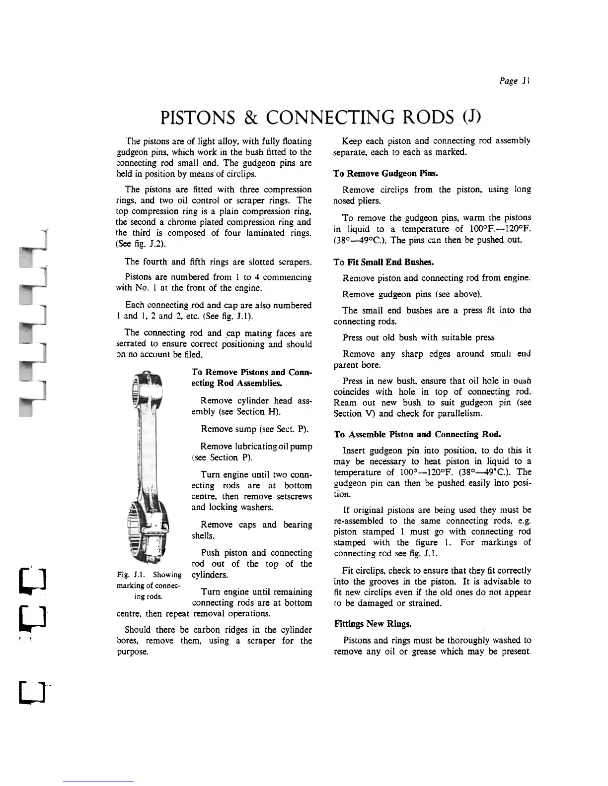
Each connecting rad and cap are also numbered
I and I, 2 and 2, etc. (See fig. J.1).
The connecting rad and .cap mating faces are
serrated la ensure correct positioning and should
on no account be filed.
To Fit Small End Bushes.
Remove piston and connecting rad from engine.
Remove gudgeon ping (see above).
The small end bushes are a press fit into the
connecting rods.
Press out aId bush with suitable press
Remove any sharp edges around smal! elld
parent bare.
Press in new bush. ensure that oiI hole Ul bu:ih
coincides with hole in top of connecting rad.
Ream out new bush to guit gudgeon pin (see
Section V) and check for parallelism.
To Remove Pistons and Conn-
ecting Rod Assemblies.
Remove cylinder head ass-
embly (see Section H).
Remove sump (see Sect. P).
Remove IubricatingoiJ pump
(see Section P).
Turn engine until two conn.
ecting roos are at bottom
centre. then re move setscrews
and locking washers.
Remove caps and hearing
shells.
l1
~,
Push piston and connecting
rad out of the top of the
cylinders.
To Assembie Piston and Connecting Rod.
Insert gudgeon pin into position. to do this it
may be necessary to heat piston in liquid to a
temperature of looo-120oF. (38°-49"C.). The
gudgeon pin can then be pushed easily into posi-
tion,
Tf original pistons are bejag used they must be
re-assembled to the same connecting rods. e.g.
piston stamped I must go with connecting rad
stamped with the figure 1. For markings of
connecting rad see fig. J .1.
Fit circiips. check to ensure that they fit correctly
into the grooves in the piston. Tt is advisable to
fit new circiips even if the oid ODes do not appear
to be damaged or strained.
u
Fig. J.1. Showing
marking of connec-
. d Turn engine until remaining
mg ro s.
connecting rods are at bottom
centre. then repeat removal operations.
Should there be carbon ridges in the cylinder
aDres. remove them. using a scraper for the
purpose.
~-
, . i
Fittings New Rings.
Pistons and rings must be thoroughly washed to
remove any oil or grease which may be present.
u-