~
.
Page S3
Fue/ lnjection System-continued
..,
-
..,
u
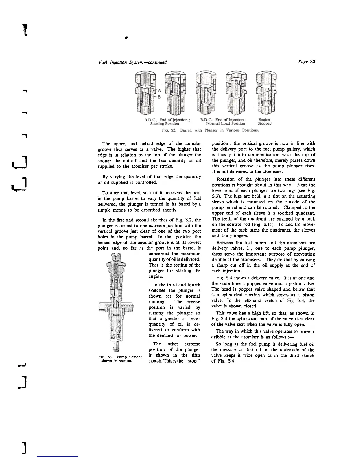
The upper, and helical edge of the annular
groove thus serves as a valve. The higher that
edge is in relation to the top of the plunger the
sooner the cut-oir and the less quantity of oil
supplied to the atomiser per stroke.
By varying the level of that edge the quantity
of oil supplied is controlled.
1
~
To alter that level, so that it uncovers the port
in the pump barrel to vary the quantity of fuel
delivered, the plunger is turned in its barre! by a
simple means to he described shortly.
In the first and second sketches of Fig. S.2, the
plunger is tumed to one extreme position with the
vertical groove just clear of anc of the two port
holes in the pump barrel. In that position the
helical edge of the circular groove is at its lowest
point and, so far as the port in tbc barrel is
concemed the maximum
quantity of oil is delivered.
That is the setting of the
plunger for starting tbc
engine.
In the third and fourth
sketches the plunger is
shown set fot normal
running. The precise
position is varied by
tuming the plunger so
that a greater or lesser
quantity of oil is de-
livered to conform with
the demand for power.
The otber extreme
position of the plunger
FIG. SJ. Pump element is shown in the fifth
shown in section. sketch. This is the" stop .,
position : the vertical groove is now in line with
the delivery port to the fuel pump gallery, whicb
is thus put into communication with the top of
the plunger, and oil therefore, merely passes down
this vertical groove as the pump plunger rises.
It is not delivered to the atomisers.
Rotation of the. plunger into these different
positions is brought about in this war. Near the
lower end of each plunger are two lugs (see Fig.
5.3). The lugs are held in a slot on the actuating
sleeve which is mounted on the outside of the
pump barrel and can be rotated. Clamped to the
upper end of each sleeve is a toothed quadrant.
The teeth of the quadrant are engaged by a rack
on the control rad (Fig. 5.11). To and fro move-
ment of the rack turns the quadrants, the sleeves
and the plungers.
Between the fuel pump and the atomisers are
delivery valves, 21, one to each pump plunger,
these serve the important purpose of preventing
dribble at the atomisers. They do that by causing
a sharp cut off in the oil supply at the end of
each injection.
Fig. 5.4 shows a delivery valve. It is at one and
the same time a poppet valve and a piston valve.
The head is poppet valve shaped and below that
is a cylindrical portion which serves as a piston
valve. In the left-hand sketch of Fig. 5.4, the
valve is shown closed.
This valve bas a high lift, so that, as shown in
Fig. 5.4 the cylindrical part of the valve rises clear
of the valve scat when the valve is fully open.
The war in which this valve operates to prevent
dribble at the atomiser is as follows :-
50 long as the fuel pump is delivering fuel oil
the pressure of that oil on the underside of the
valve keeps it wide open as in the third sketch
of Fig. 5.4.
~
J
]
 Loading...