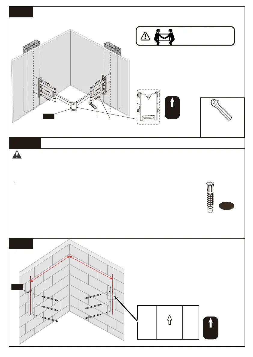
Install the arm and wall plate using lag
screws [A1] and washer [A2]. Tighten
the lag screws [A1] only until the
washers [A2] are pulled firmly against
the wall plate.
2A-4
A1
A2
1/2 in.(13mm)
Socket Wrench
(Not lncluded)
HEAVY! You may need
assistance with this step.
UP
2B-1
WARNING:
Wall
Anchor
A3
Step
2B
Solid Concrete or Concrete Block Option
●Avoid potential personal injury or property damage! DO NOT over-tighten the lag
screws [A1]. Tighten the lag screws [A1] only until the washers [A2] are pulled firmly
against the wall plate.
Position the wall plate template [05] at your
desired height, level the wall plate template
[05] and mark the pilot hole locations.(The
distance between the center location and the
corner of wall should be 525mm/20.6 in.)
UP
UP
05
05
●Ensure the arm and wall plate [01] is securely fastened to the wall
before continuing to the next step.
● Any material covering the wall must not exceed 5/8 in. (16 mm)
● Mount the arm and wall plate [01] directly onto the concrete surface
● Minimum solid concrete thickness: 203 mm (8 in.)
● Minimum concrete block size: 203 x 203 x 406 mm (8 x 8 x 16 in.)
● Never drill into the mortar between blocks.
525mm/20.6 in.
525mm/20.6 in.
UP
01 02 03 04 05 06 07 08 09 10 11 12 13 14