PKD24B INSTALLATION & OPERATION MANUAL Rev. 11.09 Page
1.2. PKD24B Operational Cycle
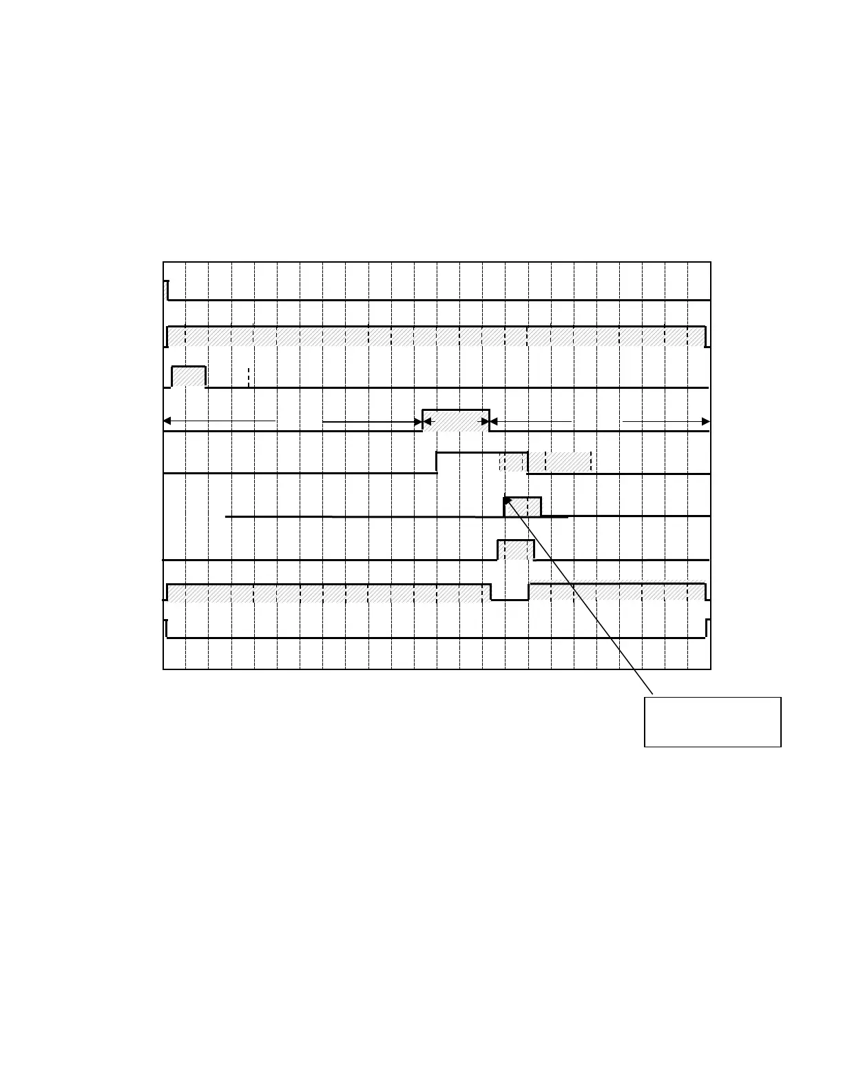
The PKD24B Operational Cycle has a total cycle time of 2 minutes (120 seconds). The
Timing Diagram and the steps listed below detail the individual functions that are
executed during each Operational Cycle.
Seconds: 0 10 20 30 40 50 60 70 80 90 100 110 120
1. With the machine powered up, toggling the START switch begins a cycle.
a) Toggling the START switch energizes both the cam timer motor and the instant
start relay. The instant start relay latches ON the power to the cam timer motor so
that the START switch can be released a moment after it has been toggled without
the cam timer motor losing power.
b) After about 2 seconds, Cam 1—the Start cam—latches ON the power to the cam
timer motor and drops out the instant start relay. The cam timer motor continues
to run for a total of 2 minutes, at which time it switches OFF—resetting the cam
timer—and waits for the next start command.
Drain/Rack
Pump Motor
Heater
Instant
4sec. delay following
the drain cycle to