8
Serial Interface
‗Serial‘ MUST be selected on activation otherwise it will not operate.
The PM24 comes standard with Securitel / serial interfaces to suit:
Tecom
MCM Icon
C & K ( Sierra STU )
Siemens
Cardax / Gallagher (IFM-CDX required)
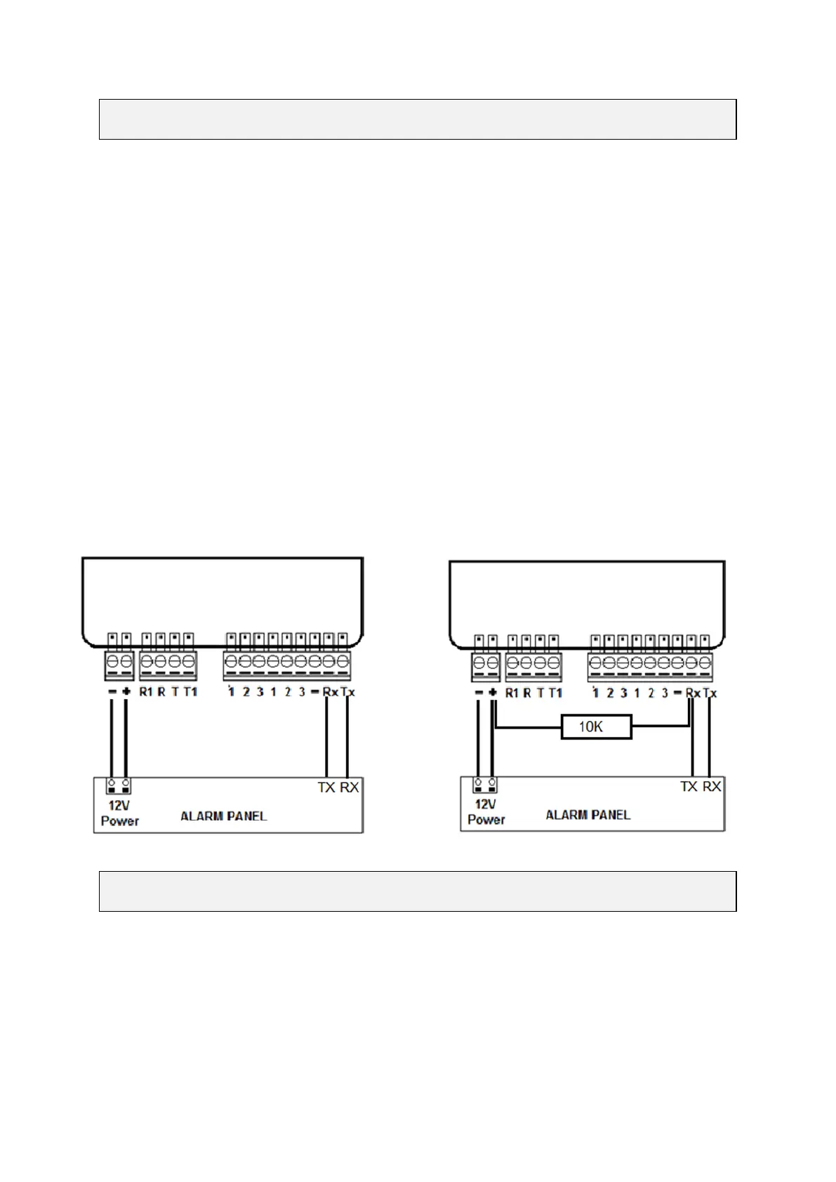
Concept (10K resistor must be fitted between +12v and Rx)
Serial LED [Green - Blink] to indicate successful Securitel or serial interface.
Wiring Diagram for Serial Connection Additional Wiring for Concept STU Connection
Transmission Delay Times
Messages originating from the Alarm Panel are forwarded immediately.
Alarm Panel ‗Dialler Interface Lead Fail‘ is sent if not restored within 90 seconds.
Arm / Disarm reporting may occur at the end of exit delay (Pocket Secure).
PM24 Installation Manual v1.1 RDCCO_2204_E_IN