VB230/400-6/25/30L (LP) 23
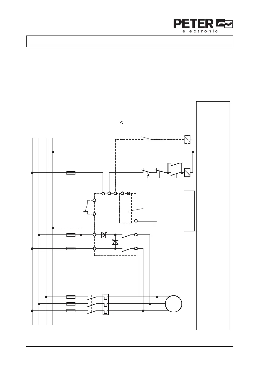
14. Typical connections
14.1 Connection diagram
M
3~
U
V
W
(T1) (T2)
(T3)
(L1) (L2)
(X1) (X2)
(X7)
F2F1 F3
Normally closed contact
of K1 not required.
F4
OFF
ON
K1
K1
K1
F4
L1
L2
L3
N
(X10)
(X11)
(X5)
(X6)
Interlock
Fault signal
Y-contactor
K1
only available
with
circuit-board
version
In case of a fault, the fault
signaling contact is open.
X7 in the case of systems
with Y - starting, X7 can
be used for controlling
the Y - contactor during braking
1L1 3L2
2T1 4T2 6T3
( ) connection terminals
at circuit-board version
X3 X4
X5
X6
X7
The limit values for emitted interference according to the applicable device standards do not rule out the possibility that receivers and susceptible
electronic devices within a radius of 10m are subjected to interference. If such interference, which is definitely attributable to the operation of the
braking devices "VB", occurs, the emitted interference can be reduced by taking appropriate measures.
Such measures are, e.g.:
To connect reactors (3mH) or a suitable mains filter in series before the braki
ng
device, or to connect X-capacitors (0.15μF) in parallel to the
supply voltage terminals.
EMC
Really ensure correct terminal-phase connections
between input of braking device (L1,L2) and output
of braking device (T1,T2).
VB 230 - ...