16
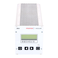
The Display And Control Unit DCU is a universal component for the control and monitoring of
PFEIFFER vacuum pumps and drive units.
Depending on the configuration of your components further operating instructions are included
in the delivery consignment (please see the table). If, despite every effort by us, information on
your products is missing please get in touch with your local Pfeiffer representatives or call us on
the hotline shown on the back cover page. All operating instructions are also available as PDF
files at www.pfeiffer-vacuum.net.
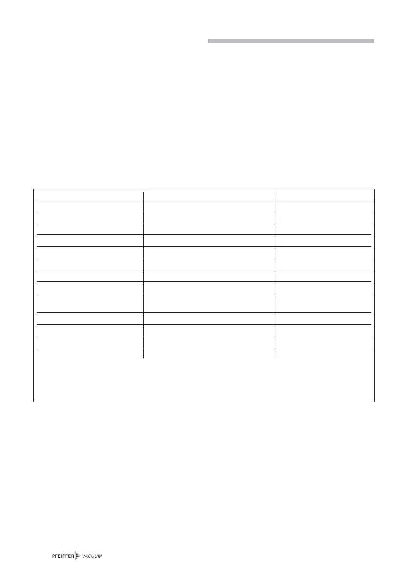
The following operating instructions are available for the range of pumps which come with DCU
control units:
9. Supplementary Information
PPrroodduucctt DDeeffiinniittiioonn NNoo.. OOppeerraattiinngg IInnssttrruuccttiioonn
Vacuum pump Description of the Pump dependend to the pump typ
1)
DCU 001, 100-600 Description of the controller PM 0477 BE
Operating turbo pump with DCU Operating definition/parameter PM 0547 BE
TPS 100, 200, 300, 600 Description of the mains power unit PM 0521 BE
Housing heating turbo pump Description of the housing heating PM 0542 BE
Air cooling turbo pump Description of the air cooling PM 0543 BE
Water cooling turbopump Description of the water cooling PM 0546 BE
Backing pump relay box
2)
Description monitoring of the backing p. PT 0030 BE
Temperature Management Description heating of the
System TMS pre vacuum section of the turbo pump PT 0099 BE
RS 232/485 Pfeiffer Vacuum Protocol PM 0488 BE
RS 232/485 Description of the interface PM 0214 BE
Level converter RS 232/RS 485 Pump monitoring via RS 232 PM 0549 BE
TVF 005 Description of the vent valve PM 0507 BE
1)
Numbers can be supplied by PFEIFFER Service.
2) Only for rotary vane vacuum pumps.