6
Fitting The Splinter Shield
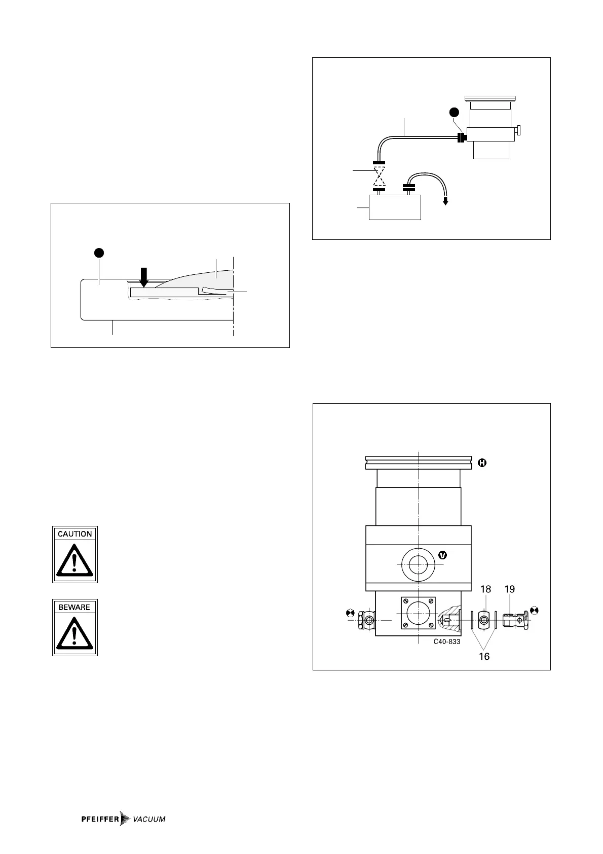
Insert the splinter shield in the high vacuum flange in such a
way that the corrugation of the strainer points outwards.
➡ Bend the clamping lugs slightly outwards so that
subsequently the splinter shield is seated firmly in the high
vacuum flange (to avoid noise).
➡ Insert the splinter shield in the high vacuum flange while
pressing the clamping lugs slightly inwards.
➡ Press the outer ring of the splinter shield up to the limit
stop point in the high vacuum flange.
12a
12
H
Inserting the splinter shield
12 Splinter shield
12a Clamping lug
3.3. Connecting The Fore-Vacuum Side
Backing pump: Vacuum pressure ≤ 5 mbar
Recommendation: Oil-Free Diaphragm Pump or Rotary
Vane Vacuum Pumps from the PFEIFFER
range (note installation position,
turbopump, see Section 3.2.).
Connecting the backing pump
All connections of the fore-vacuum line: with the usual small
flange components or hose screw connections.
Be sure to conduct away the exhaust gases
from the backing pump. Do not reduce the free
cross section of the fore-vacuum flange with
following components.
The exhausted process gases and vapours can
represent a health hazard and can also be envi-
ronmentally damaging.
Comply with all the gas manufacture's safety
instructions.
➡ Fit the vacuum safety valve in the fore-vacuum line (in
PFEIFFER rotary vane vacuum pumps already integrated).
This prevents vacuum chamber venting via the backing
pump.
➡ With rigid pipe connections: Fit bellows in the connecting
line to reduce vibration.
➡ Backing pump power connection: See operating
instructions for the electronic drive unit.
22
23
21
V
≤ 5 mbar
DN 16 ISO-KF
G1/4”
Connecting the backing pump
21 Backing pump
22 Vacuum safety valve
23 Suction line
3.4. Connecting The Cooling Unit
The turbopump is convection-cooled as standard.
Where ambient temperatures exceed 30 °C or with heated
systems, the pump should be operated with air or water coo-
ling.
Water cooling is mandatory where temperatures
exceed 35 °C.
Water Cooling (Accessory)
See “Accessories” for the cooling water parts set.
Cooling water either
– From the cooling water mains, or
– from Recycled Water Cooling Unit TZK with closed
circuit.
Cooling water from the cooling water mains
Cooling water must be filtered to prevent deposits forming in
the pump.
Minimum cooling water requirements:
Mechanically clean, optically clear, no turbidity, no sediment,
chemically neutral, temperature > dew point.
Connecting parts set for cooling water
16 USIT ring
18 Hose nozzle
19 Hollow screw


 To Next Page