8
3.7. Connecting The Electronic Drive Unit
Voltages of >100 V can be present on the open
electrical contacts on a slowing down pump.
There is danger of an electrical shock if the
contacts are touched.
Disconnect the plug to the electronic drive unit
only once the pump is completely at rest and the electronic
drive unit has been disconnected from the mains.
➡ Plug in connecting cable between the electronic drive unit
and the turbopump. For details please see the operating
instructions for the electronic drive unit.
51
53
52
50
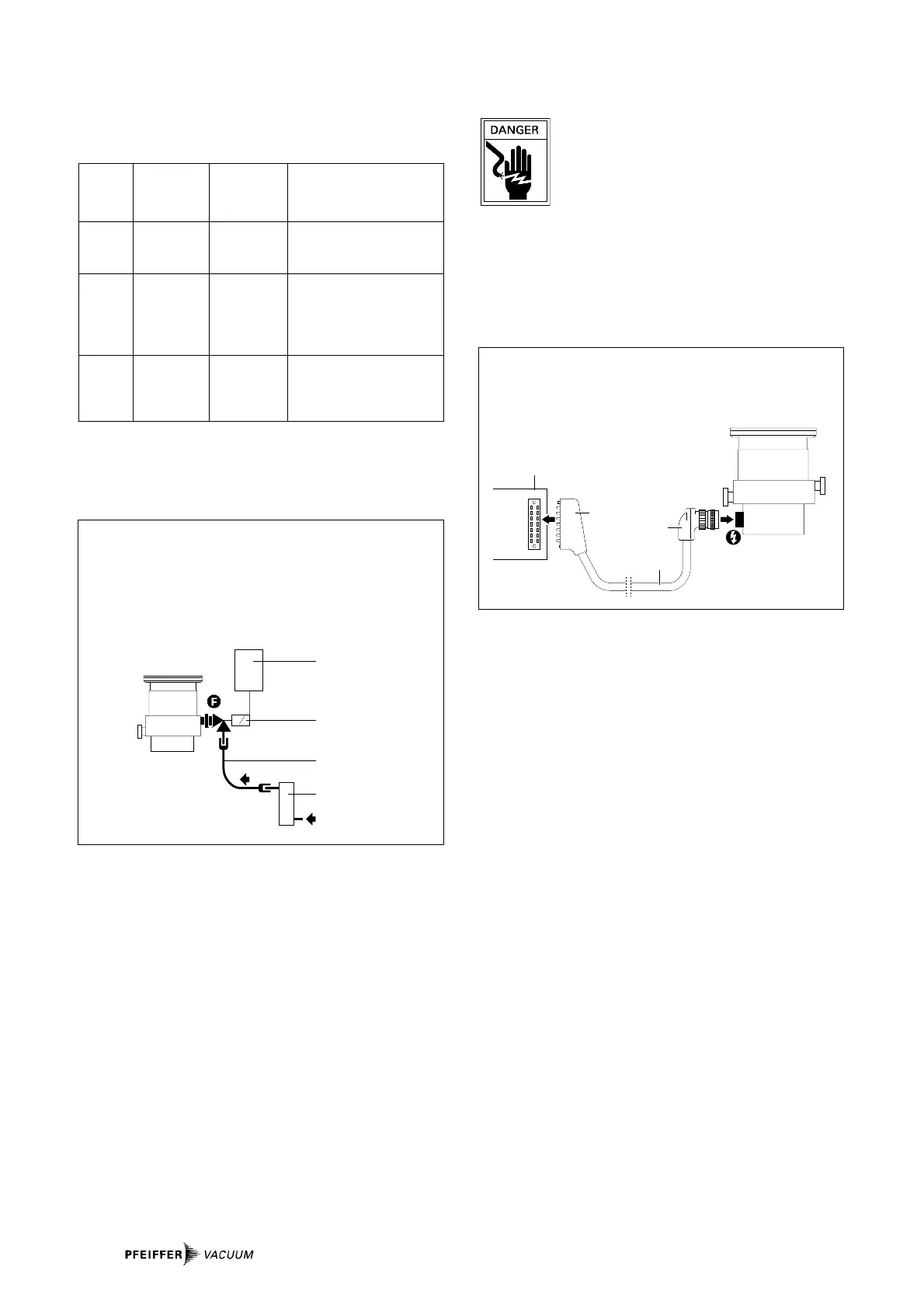
Connecting electronic drive unit to the turbopump
50 Electronic Drive Unit TCP
51 Male multipoint connector
52 Connecting cable
53 Bayonet plug --> turbopump
3.8. Conncting The Sealing Gas Valve
To protect the pump, particularly where corrosive or dust pro-
ducing processes are involved, it is necessary to use sealing
gas. Connection is made via the sealing gas valve (please see
”Accessories”).
Please refer to Operating Instructions PM 800 229 BE for
details on installling the sealing gas valve and adjusting the
sealing gas flow.
Please refer to Section 8.1. ”Dimensions Diagram” for the
sealing gas connection.
3.6. Connecting The Venting Valve
– The venting valve provides automatic venting in the event
of a power failure and switching off.
Connecting the venting valve
41 Venting control unit
42 Venting valve
43 Connecting hose
44 Drier TTV 001
Power connection
Please refer to the operating instructions of the respective
unit.
Venting Control Unit Electronic Venting Procedure
Valve Drive After Switch OFF Or
Power Failure
TSF 010 not independent Immediate;
required Venting valve remains open
TSF 012 not TCP 015/ Delayed (venting begins at
required 380/121 approx. 20% of the rated
rotation speed) venting valve
remains open
TVF 012 TCF/TCV 103 TCP 380/121 Delayed: adjustable
(not with (with TCS 304)
TCP 015)
Fitting the venting valve
Please refer to the operating instructions of the respective
unit. Use Adapter PM 033 737-T where flange size DN 10-KF is
involved.
 Loading...