7
Oxygen content: max 4 mg/kg
Chloride content: max. 100 mg/kg
Carbonate hardness: max. 10 °dH
Potassium permanganate consumption: max. 10 mg/kg
Carbon dioxide: Undetectable
Ammonia: Undetectable
pH-value: 7 – 9
Fore-line over pressure: max. 6 bar
Minimum flow rate at gas load max.: 50 l/h bei 15 °C
Connecting to the water mains
➡ Fit dirt trap (accessory) in the fore-line.
➡ Using circlips, connect fore-line to one of the two cooling
water connections.
➡ Fit Cooling Water Monitor TCW 002 (accessory) in the
return line.
➡ Connect return line to the other turbopump cooling water
connection.
➡ Tighten all circlips and ensure hose lines are seated firmly.
➡ Tighten the hollow screws on the cooling water
connection to a torque of 20 Nm.
Cooling from the water mains
3 Cooling water connection
31 Fore-line
32 Return line
33 Dirt trap
34 Cooling Water Monitor TCW 002
Cooling with the recycled Water Cooling Unit TZK
(Accessory)
Connecting to the TZK
A dirt trap in the pipeline is not permissible.
All other steps as for connection to the water mains.
Cooling with the recycled Water Cooling Unit TZK
3 Cooling water connections
34 Cooling Water Monitor TCW 002 in the return line
35 Recycled Water Cooling Unit TZK
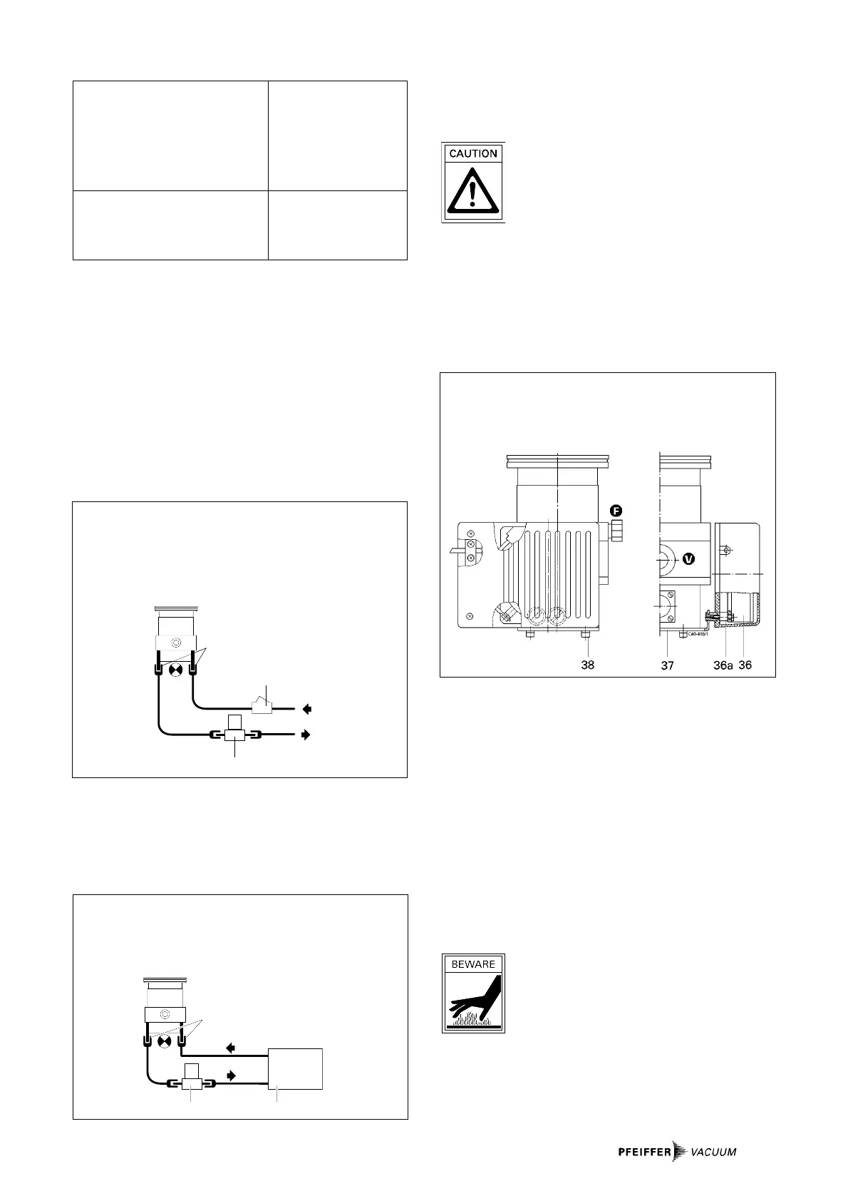
Air Cooling (Accessory)
See “Accessories” for air cooling parts set.
Air cooling permissible only if ambient tem-
perature < 35 °C.
Ensure adequate air circulation and ventilation.
Fitting the air cooling
➡ Place turbopump on its high vacuum flange (blank flanged
so that the sealed surface is not damaged).
➡ Unscrew rubber feet from the base of the pump.
➡ Screw air cooling onto the holder with 4 M5 screws and
spring washers onto the turbopump. The fan must be
parallel to the axis fore-vacuum connection - venting
connection. See illustration below.
Fitting the air cooling
36 Fan
36a Buffer
37 Holder
38 M5 screw with spring washers (4x)
Power connection, air cooling
Please see the operating instructions for the Electronic Drive
Unit TCP 015.
3.5. Connecting The Casing Heating Unit
The attainment of final pressures is accelerated when turbo-
pumps and vacuum chambers are baked out.
The heating duration is dependent on the degree of dirt and
on the required final pressure level. The heating duration
should be at least 4 hours.
➡ Secure heating sleeve beneath high vacuum flange.
High temperatures are generated when
turbopumps and vacuum chambers are baked
out. There is a danger of burns resulting from
touching hot parts, even after the casing heating
has been switched off.
Ideally, the heating sleeve, pump casing and vacuum
chamber should be insulated during installation. Do not touch
the heating sleeve, pump casing and vacuum chamber during
the baking out process.