OperatingInstructions&PartsManual
HorizontalRotaryTables
DividingPlates
Pg. 5
Toassemblethedividingplateattachmenttotherotarytable,removehandwheel(Ref.No.46).Bolttherequiredplatetothe
collarusing4screws(Figure3,RefNo.3).Slidethesector(Figure3,Ref.No4)overthewormshaftandeccentricsleeve
(Ref.Nos.31and37)withthesectorscrewexposed.Securesectorbyslidingspringwasher(Figure3,Ref.No.5)againstsector
andintoslotineccentricsleeve.
Slidecrankarm(Figure3,Ref.No.7)overflatsatendofwormshaftandsecurewithspacerandnut(Ref.Nos.50and51).
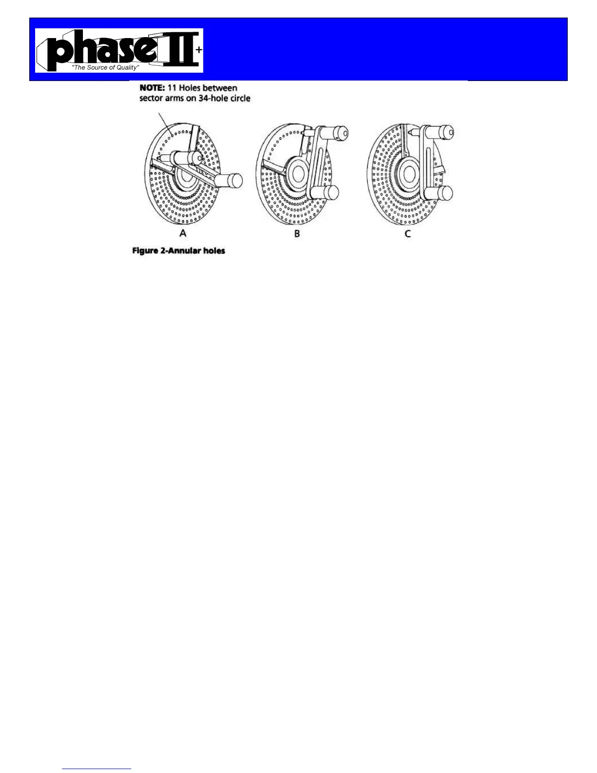
Spreadthesectorarmssothatexactly11holesonthe34holecirclearebetweenthearms(seeFigure2).Tightenthesector
screw.
1. RotatethesectorsothatthesectorarmisagainsttheplungerassemblyasinFigure2A.
2. Rotatetheplungerassemblyclockwise5fullrotationsand10/34ofthearotationbyplacingtheplungerassemblyagainst
thesectorarmasinFigure2B.
3. RotatesectorclockwisesothatfirstarmisagainstplungerassemblyasinFigure2C.
Repeatsteps1,2and3foreachdivision.Thedividingchart(Page4)showsthatfor19divisionstheplatewith38holesis
requiredandeachdivisionneeds4fullrotationplus28/38ofarotation.Thedividingchartshowsthatfor53divisions,each
divisionrequires1and37/53rotations,etc.Forevendivisionsof90(2,3,4,5,6,9,10,15,18,30and45)simplyrotatethe
crankarmrequirednumberoffullturnsusingthesameholeonanyplate.
Maintenance
RefertoFigure4thru8.
WormShaftAdjustment
Toadjustforwearinthewormshaft,thelocknut(Ref.No.35)mustbeadjusted.
Removehandwheel(RefNo.46)andspacer(RefNo.36)Tightenlocknutuntilplayisremovedfromengagedwormshaftand
clampingsurface.Donotover‐tightenlocknut.Replacespacerandhandwheel.
EccentricSleevelimitscrewadjustment
Thethreadedpin(RefNo29)regulatestherotationateccentricsleeve.Ifthewormshaftdoesnotengagetableproperlywhen
verniercollarisrotatedcounterclockwise,thenunscrewsetscrew(RefNo,28)andadjustthethreadedpinuntilproper
engagementisachieved.
Note:Formodel221‐308setscrew(RefNo.28)andthreadedpin(RefNo.29)islocatedinlowerrightcornerofthebottomof
thebasecasting(RefNo.1)
 Loading...