DEFAULT [UNITS]
(MIN - MAX)
1.1.4.2
Deceleration
Curve Select
@
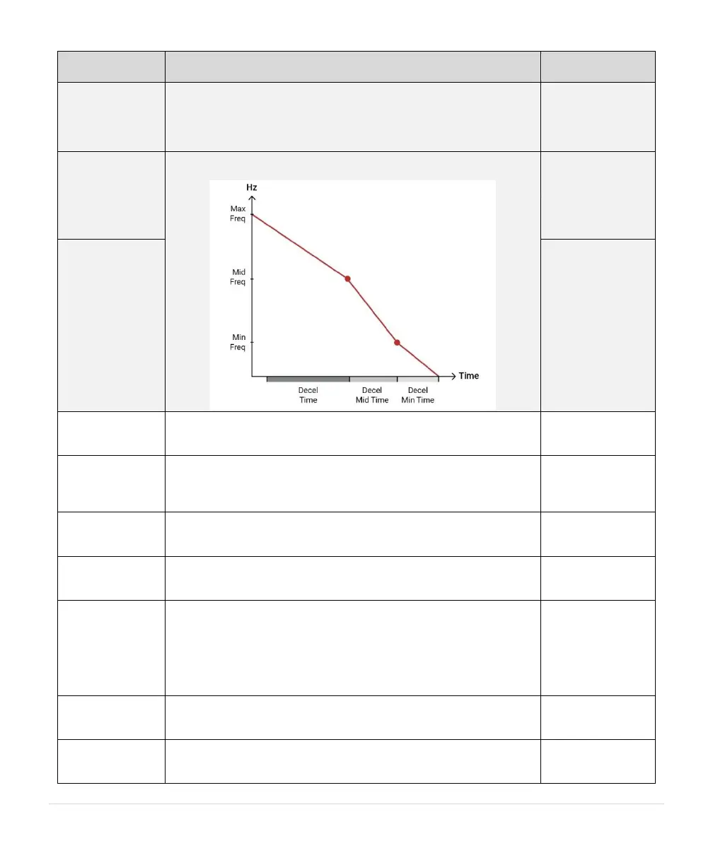
Select how many points occur on the deceleration ramp profile.
max – 0: linear ramp from 1.1.2 MAX FREQUENCY to zero.
max – min – 0: 1.1.1 MIN FREQUENCY acts as a mid-point between
1.1.2 MAX FREQUENCY and zero.
max – mid – min – 0: Adds an additional mid point to the ramp profile.
1.1.4.3
Deceleration
Min Time
@
Use these parameters to set a multi-speed deceleration profile according
to the chart below. 1.1.11 COAST TO STOP must be NO.
1.1.4.4
Deceleration
Middle Time
@
1.1.4.5
Deceleration
Middle
Frequency
@
Setting for motor overload protection, Trip Class 10 curve.
Drive Rated Current
(3 A – 105% Drive
Rated Current)
Unit shuts down when output current goes below the set value
(commonly used for dry well protection). Value can be adjusted while
load is running. Drive must be running at 1.1.2 MAX FREQUENCY to
engage this protection.
Disabled
(0 A – 90%
Rated Current)
Selects between coast to stop or ramp to stop. Ramp profile is controlled
by parameter 1.1.4 DECELERATION PROFILE. YES = coast to stop,
NO = ramp to stop.
1.1.12 Ground
Fault Sensitivity
Detects fault between any output line and earth. Sensitivity to fault
detection is adjustable to avoid nuisance trips. Lower value equals lower
sensitivity to fault detection. (0 = Disabled)
ENABLE THIS FEATURE WITH SUMBERSIBLE PUMPS. Frequency
will ramp from stop to the value set by parameter 1.1.1 MIN
FREQUENCY in one second. Submersible pumps suffer damage to the
thrust bearing if operated below 30 Hz for more than one second.
YES = one second ramp time from stop to minimum frequency
NO = linear ramp from stop to 1.1.2 MAX FREQUENCY. 1.1.1 MIN
FREQUENCY is observed while motor is running.
Reverses motor direction by changing sequence of output phases.
Default: Standard
ABC
Reverse ACB
Output voltage on main motor terminals. This can be used on DXL drives
ONLY to decrease voltage. This can be used on LHX drives however, to
decrease or increase output voltage.
240 V (100-270)
480 V (200-530)