DEFAULT [UNITS]
(MIN - MAX)
1.1.16 Switching
Frequency
$
Switching frequency of the IGBT inverter module. Range varies based on
the rated HP of the drive. Also known as Carrier Frequency.
5-100 HP:
4 kHz (2k-5k)
125-400 HP:
2 kHz (1.5k-5k)
600+ HP:
1.5 kHz (1.5k-5k)
2XD:
3 kHz (2k-8k)
1.1.17 Overload
Derate Enable
$
During heavy startups, drive frequency will slow down to avoid Output
Overload fault. The screen will say OVERLOAD DERATE when
conditions apply. Setting can be disabled or set to react SLOW,
MEDIUM, or FAST.
1.1.18
Overcurrent
Derate Enable
$
Drive frequency will slow down to maintain 1.1.9 OVERCURRENT LIMIT.
Screen will display OVERCURRENT DERATE when conditions apply.
1.1.19 Over
Temp Derate
Enable
$
Drive frequency will slow down to avoid drive over temperature fault.
Screen will display OVER TEMP DERATE when conditions apply.
Press ENTER to see the following parameters related to V/F Control.
Controls the relationship between voltage and frequency when starting a
motor for different applications.
Standard: Voltage and frequency are proportional. Torque is constant.
Soft Start 1: Limits voltage during initial ramp to reduce inrush current.
Torque is reduced.
Soft Start 2: Exaggerated Soft Start ramp to reduce inrush current and
torque more than Soft Start 1.
Soft Start 3: Exaggerated Soft Start ramp to reduce inrush current and
torque more than Soft Start 2.
Torque Boost: Boosts voltage during initial ramp to increase startup
torque.
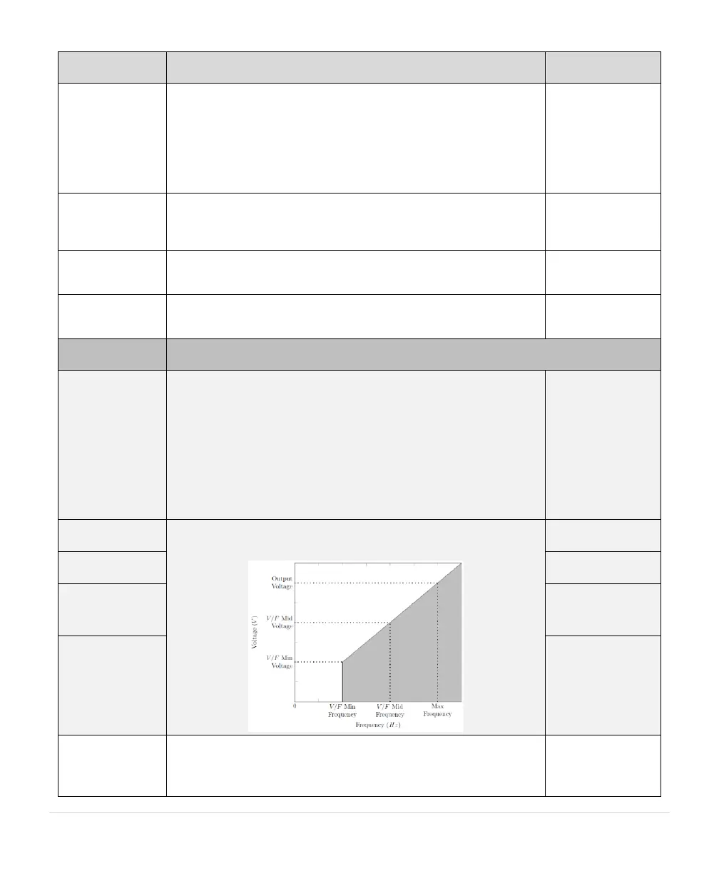
1.1.25.3 V/F Min
Frequency
Use these settings to customize the V/F ramp profile based on the
following graph. These settings can only be used when V/F Selection is
set to 5 = Custom.
1.1.25.4 V/F Mid
Frequency
240 V: 30 V (0-240)
480 V: 60 V (0-480)
240 V: 120 V (0-240)
480V: 240 V (0-480)
1.1.26 PWM
Over Modulation
@
Output voltage may be lower than the input voltage because of losses
from a filter or input reactor. Use this parameter to boost output voltage
on DXL systems if necessary. On LHX systems, increasing the
parameter 1.1.15 OUTPUT VOLTAGE is a better option.