EasyManuals Logo

Phenix Technologies 600P Series User Manual

Phenix Technologies 600P Series
26 pages
To Next Page IconTo Next Page
To Previous Page IconTo Previous Page
Page #5 background imageLoading...
Page #5 background image
6CP30/15-3
2-1
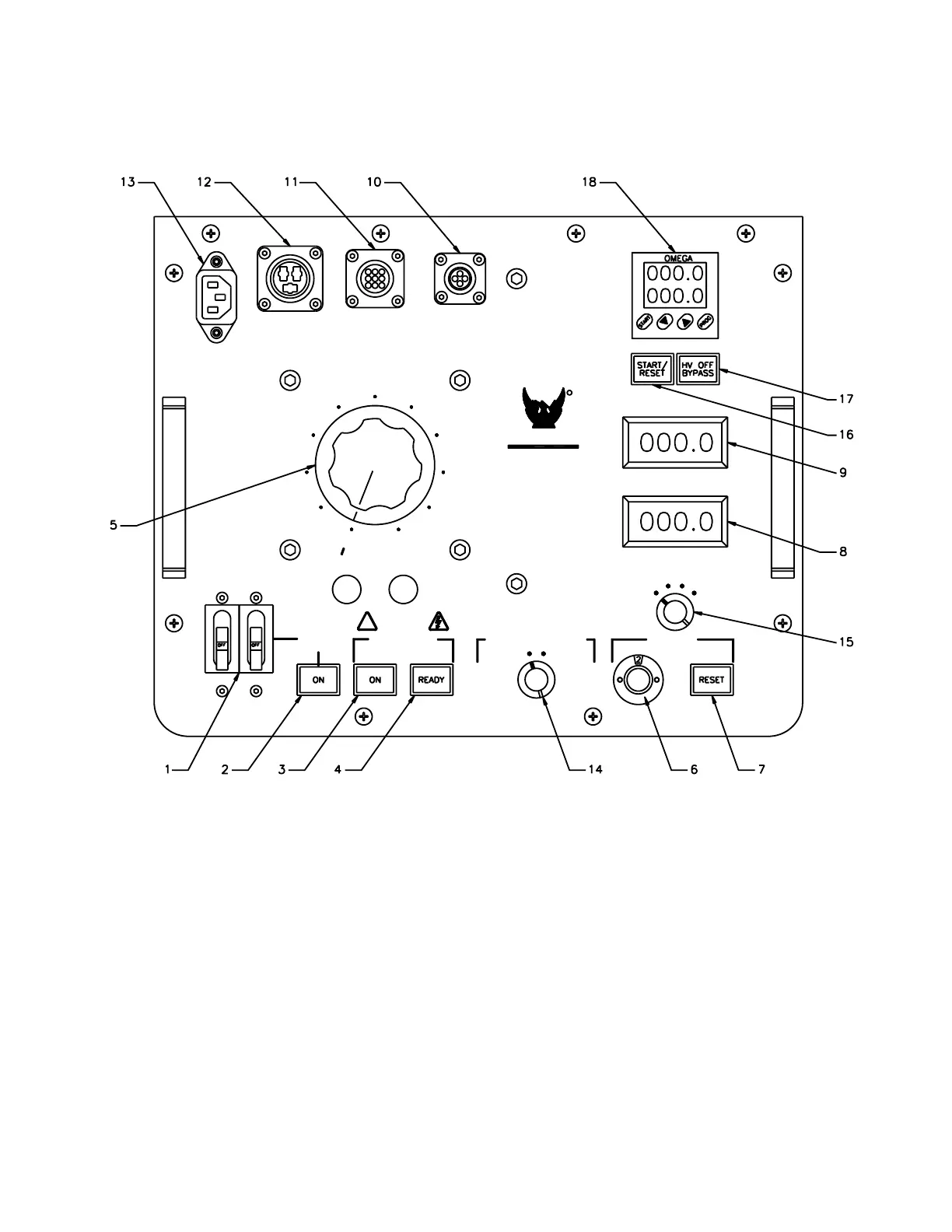
SECTION 2: CONTROLS AND INDICATORS
Figure 2-1








 
PHENIX

TECHNOLOGIES











































Control Panel: The following descriptions are keyed to Figure 2-1
1. Main Power Circuit Breaker. Turns main power of unit on and off and provides input overload protection.
2. Main Power Lamp. Illuminates to indicate input power is supplied to unit.
3. High Voltage On. Momentary switch activates power to high voltage circuits when prerequisite conditions
are met. Ready lamp (4) must be illuminated before High Voltage On switch will operate. See
requirements for Ready lamp under step 4. High Voltage On lamp illuminates to indicate high voltage
circuits are energized.

Questions and Answers:

Question and Answer IconNeed help?

Do you have a question about the Phenix Technologies 600P Series and is the answer not in the manual?

Phenix Technologies 600P Series Specifications

General IconGeneral
BrandPhenix Technologies
Model600P Series
CategoryTest Equipment
LanguageEnglish

Related product manuals