Do you have a question about the Phenix Technologies 6CP200/100-10 and is the answer not in the manual?
Critical safety warnings regarding high voltage hazards.
Essential safety practices for operating high voltage test equipment safely.
Procedures for carefully removing and inspecting the equipment after shipment.
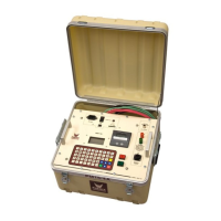
Identifies key controls and indicators on the main control panel.
Details main power, transformer power circuit breakers, and fuses.
Describes measurement divider switch and overcurrent trip.
Explains High Voltage On/Off switches and Voltage Control dial.
Describes external interlocks and timer operations.
Details transformer power input, ground points, and interconnect cables.
Explains Lundeys, input voltage selection, and HV electrodes.
How to select input voltage for single/parallel operation.
Connection point for HV output and corona shielding.
Ensuring adequate space, floor strength, and proper module positioning.
Detailed instructions for grounding the test set and its components.
Connecting external interlocks and the test object to the setup.
Connecting divider and signal/metering cables between units.
Details three possible high voltage output configurations and connections.
Explanation of Standard and Guard modes for current measurement.
Connecting for standard and guarded current measurements.
Ensuring proper setup and activating High Voltage output.
Verifying voltmeter readings and overcurrent trip functionality.
Ensuring connections are secure and area is safe before testing.
Raising voltage to desired level and recording data.
Procedure for calibrating the output voltmeter using specific settings.
Procedure for calibrating output current ranges with HV loads.
Steps to recalibrate the overcurrent circuit using capacitor load.
Adjusting voltage and current offsets for accurate readings.
General checks for control and power issues.
Diagnosing issues when high voltage cannot be turned on.
Troubleshooting inoperable overload trip functionality.
Diagnosing problems with currentmeter and voltmeter operation.
Troubleshooting lack of output voltage from the high voltage section.
Guidelines for cleaning cabinet, meter faces, and transformer surfaces.
Maintenance for control assembly, brushes, and transformer oil purity.
Means of determining dielectric strength and common test gaps.
Transformer oil quality, specifications, and handling after filling.
Precautions for anchoring and covering equipment during transport.
Recommendations for storing equipment in a warm, dry environment.
Procedure for ordering replacement parts and required information.
Information required for returning equipment and the authorization process.
| Duty Cycle | Continuous |
|---|---|
| Frequency | 50/60 Hz |
| Current Rating | 100 mA |
| Cooling Method | Air cooled |
| Output Voltage | 0-200 kV |
| Output Current | 0-100 mA |
| Voltage Rating | 200 kV |