6CP50/10-3
6-1
SECTION 6: CALIBRATION
CAUTION: Calibration should only be done by persons familiar with High Voltage testing and safety
procedures.
All calibrations have been done at the factory. Periodic calibration of the output voltmeter and output
currentmeter should be done annually.
NOTE: Refer to Electrical Diagram Section for schematic pertaining to the model number of your test set.
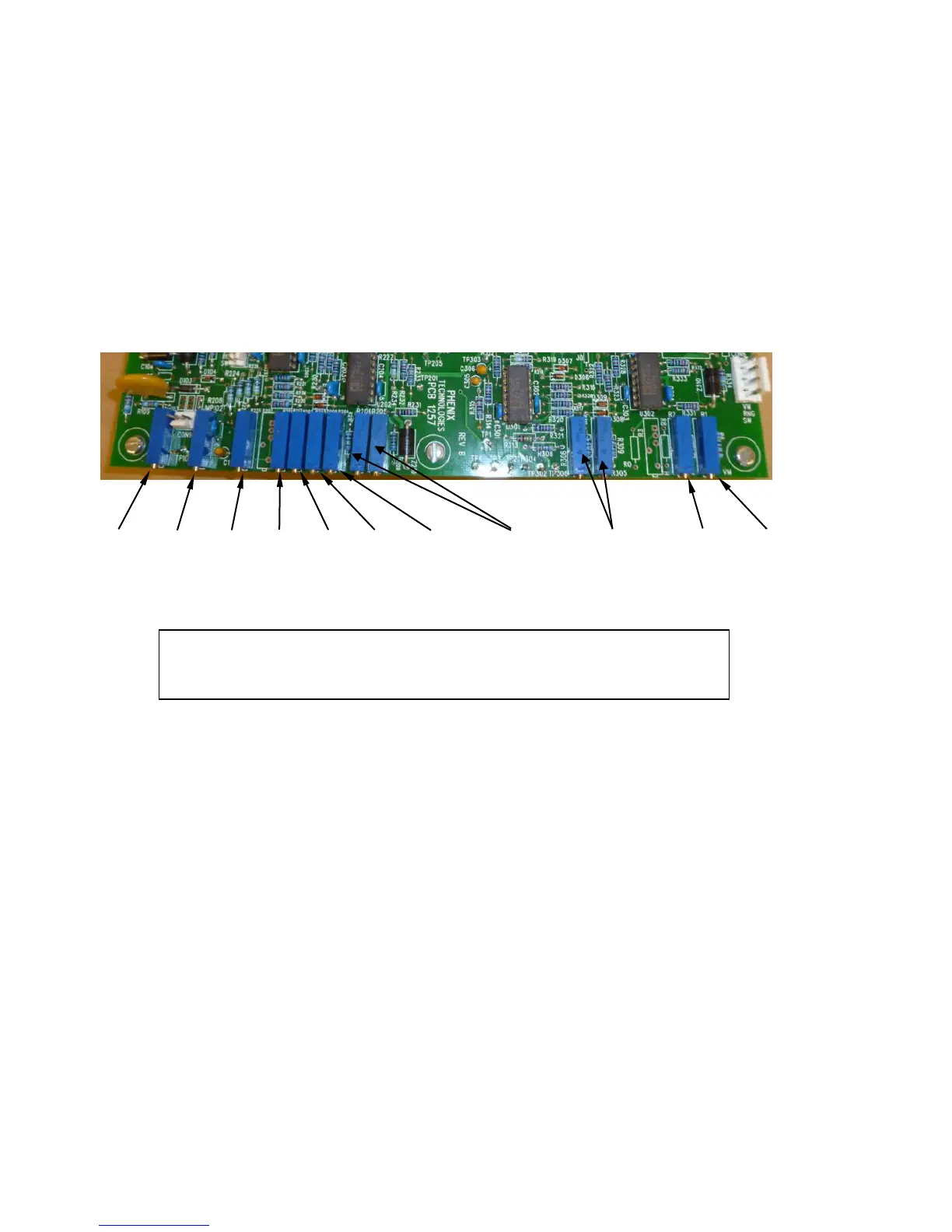
Locating the Calibration Adjustments
The calibration points are shown in the following diagram.
1. Output Voltmeter
Voltmeter is peak responding calibrated to Peak/√2 (RMS value of sine wave).
10kV Range: Connect a precision high voltage voltmeter between the 10kV output (side of tank) to
ground. Be sure the Measurement Divider switch on the control panel is in the 10kV
position. Raise the output to approximately 80% of the rated output voltage. Adjust
the reading on the panel meter (M2) by means of potentiometer R1 to a corresponding
reading. Check linearity at several points from 20% to 100% of rated tap voltage.
50kV Range: Connect a precision high voltage voltmeter between the 50kV output (top of tank) to
ground. Be sure the Measurement Divider switch on the control panel is in the 50kV
position. Raise the output to approximately 80% of the rated output voltage. Adjust
the reading on the panel meter (M2) by means of potentiometer R2 to a corresponding
reading. Check linearity at several points from 20% to 100% of rated tap voltage.
NOTE:
R205, R206, and R305, R306 are set at the factory and should not be adjusted.
 Loading...


