1-5-2 T6300DC
6. Removal of the Main CBA.
Remove six screws (S-6) and pull up the Main
CBA.
Caution !!
Discharge the Anode Lead of the CRT with the CRT
Ground Wire before removing the Anode Cap.
7. Removal of the Power Unit.
First, discharge the Anode Lead of the CRT with
the CRT Ground before removing the Anode Cap.
Disconnect the following: Anode Cap, CN501, CRT
CBA and CN571. Second, remove two screws (S-
7). Then, pull the Power Unit backward.
8. Removal of the H.V./Power Supply CBA.
Remove four screws (S-8) and pull up the H.V./
Power Supply CBA.
9. Removal of the CRT.
Remove four screws (S-9) and pull the CRT back-
ward.
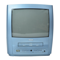
Fig. 1
EXT1/AV1
S-1
S-1
S-2
S-2
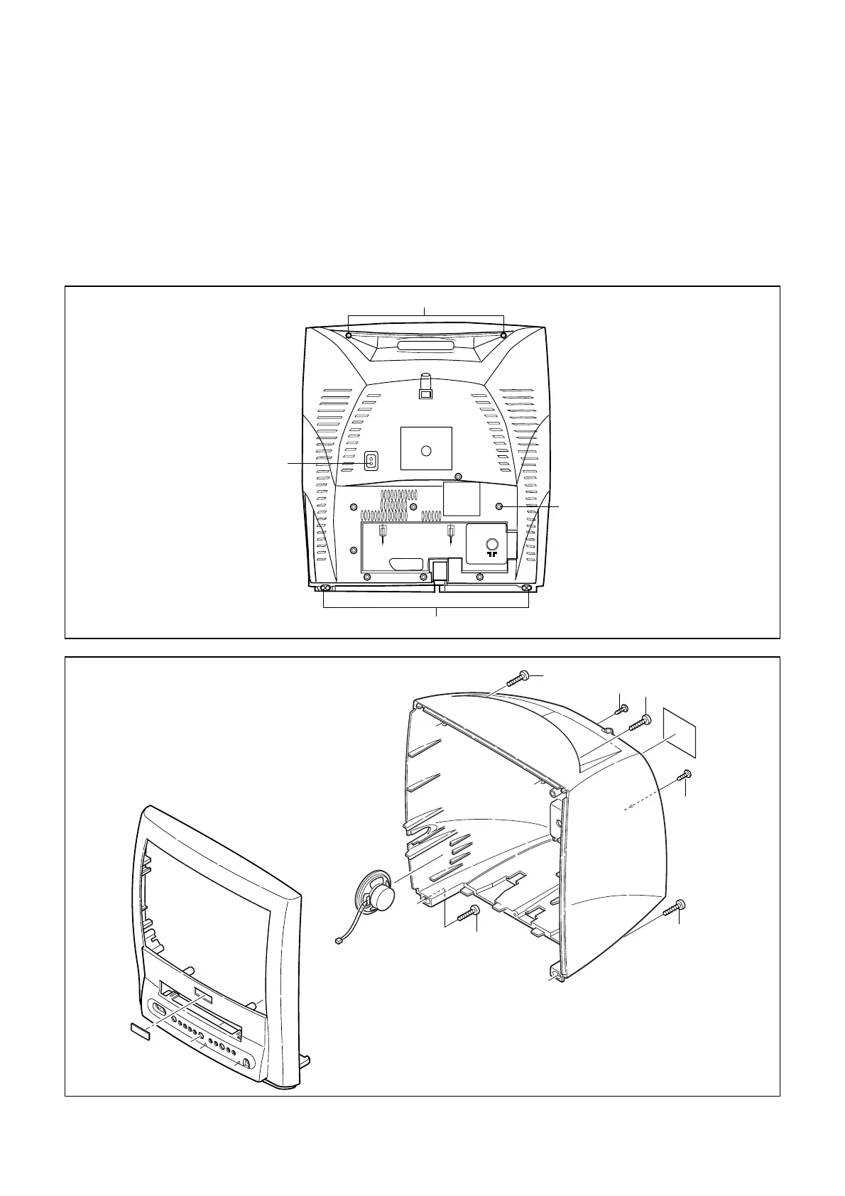
Fig. 2
[1] REAR CABINET
S-1
S-1
S-1
S-2
S-2
S-1
Screws S1 can be cross
slot or torx 10. In case of
torx please use screw
driver: 4822 395 50423.