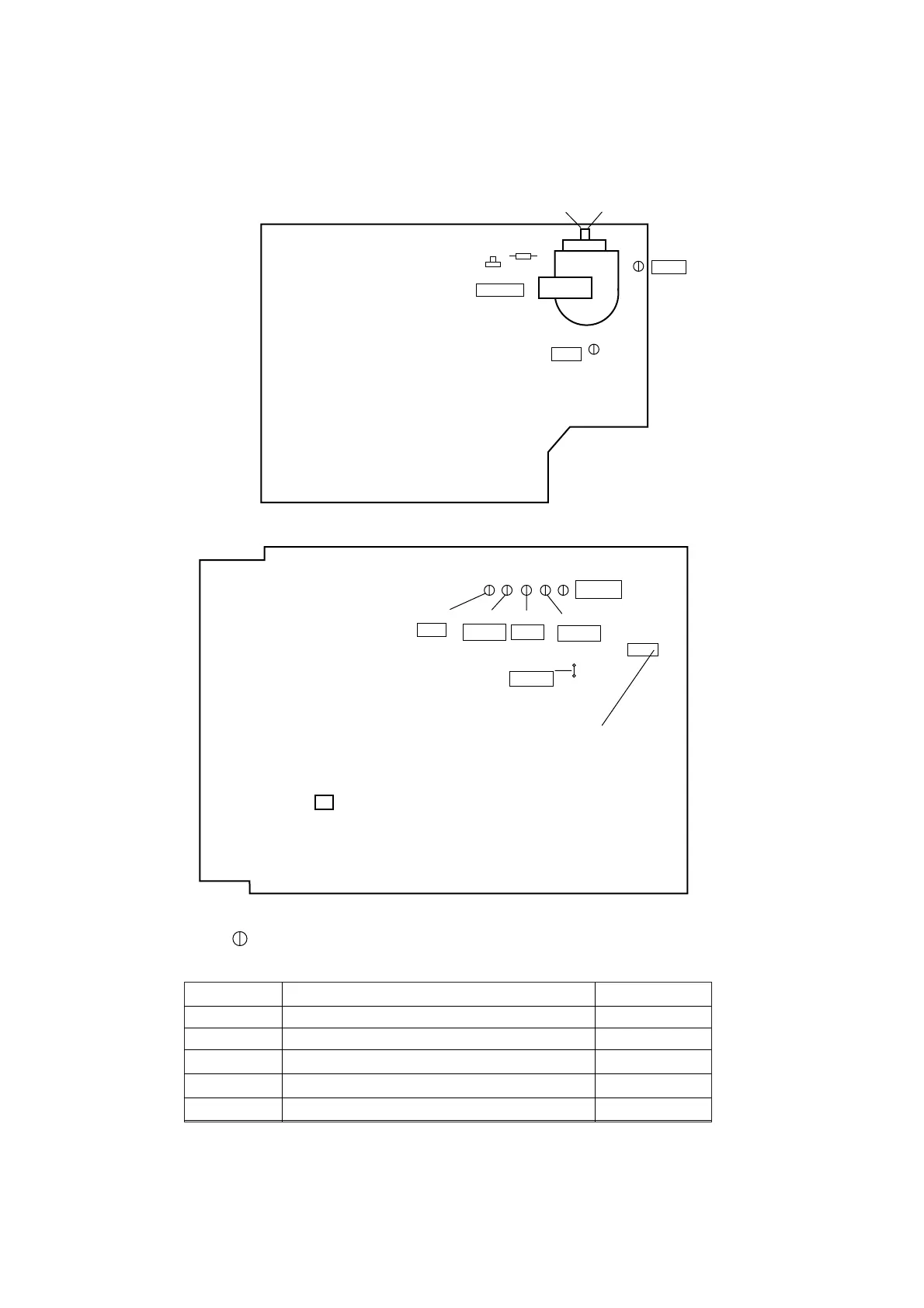
1-6-8 Z11PALEA
Main CBA Top View
TP002
RF-SW
Pin 1 of CN303
(SECAM Black Level Adjustment)
TP007
A-OUT
TP004
CPB
J219
B-OUT
TP003
V-OUT
TP001
CTL
H.V./Power Supply CBA Top View
TP504
GND
TP503
+B
VR601
+B ADJ
R583
(H Adjustment)
Focus-control
(Upper side)
Screen-control
(Lower side)
15
IC202
TEST POINT INFORMATION
: Indicates a test point with a jumper wire across a hole in the PCB.
Test Point
TP001
TP002
TP004
TP503
TP504
Used in: Page No.
Mechanical Alignment Procedures
Mechanical Alignment Procedures
Mechanical Alignment Procedures
Electrical Adjustment Instructions
Electrical Adjustment Instructions
2-3-3
2-3-3, 2-3-4
2-3-3, 2-3-4
1-6-1
1-6-1
TEST POINTS NOT USED IN ELECTRICAL ADJUSTMENTS
Adjustment Points and Test Points