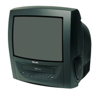
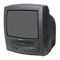
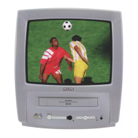
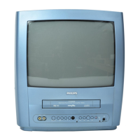
1-6-2 Z11PALEA
2. H Adjustment
Purpose:
To get correct horizontal position and size
of screen image.
Symptom of Misadjustment:
Horizontal position and
size of screen image may not be properly displayed.
Note:
R583 --- H.V./Power Supply CBA
1. Connect Frequency Counter to R583.
2. Set the unit to the VIDEO mode and no input is
necessary. Enter the Service mode.
(See page 1-6-1.)
3. Operate the unit for at least 20 minutes.
4. Press [2] button on the remote control unit and
select H-Adj Mode.
5. Press [P+/P-] buttons on the remote control unit so
that the display will change [0] to [7.]
At this moment, choose display [0] to [7] when the
Frequency counter display is closest to
15.625kHz±300Hz.
6. Turn the power off and on again.
3. C-Trap Adjustment
Purpose:
To get minimum leakage of the color signal
carrier.
Symptom of Misadjustment:
If C-Trap Adjustment is
incorrect, stripes will appear on the screen.
Note:
J219 (B-Out)--- Main CBA
1. Connect Oscilloscope to J219.
2. Input a color bar signal from RF input.
Enter the Service mode. (See page 1-6-1.)
3. Press [0] button on the remote control unit and
select C-TRAP Mode.
4. Press [P+/P-] buttons on the remote control unit so
that the carrier leakage B-Out (4.43MHz) value
becomes minimum on the oscilloscope.
5. Turn the power off and on again.
Test point Adj. Point Mode Input
R583
P+/P-
buttons
Video ---
Tape M. EQ. Spec.
--- Frequency Counter 15.625kHz±300Hz
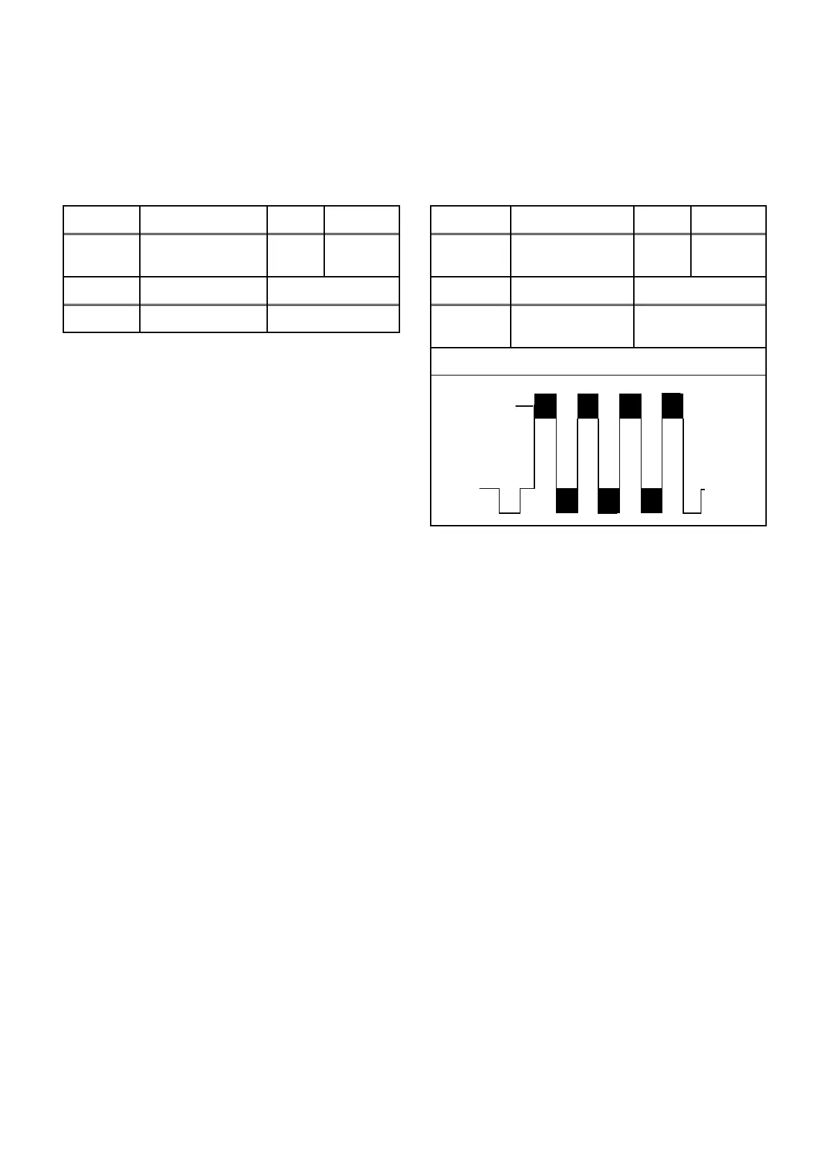
Test point Adj. Point Mode Input
J219
(B-OUT)
P+/P-
buttons
--- Color Bar
Tape M. EQ. Spec.
---
Oscilloscope
Pattern Generator
200mVp-p Max.
Figure
minimum
Fig. 1