11
TPE1.0U LA
5. Service Modes, Error Codes and Fault Finding
transmitter. This value can vary from 0 (good signal) to 127
(average signal) and to 255 (bad signal). For some
software versions, the noise figure will only be valid when
before
activating CSM.
"Active Control" is set to "medium" and "maximum"
"TUNER","AV1","AV2",
"AV3","HDMI 1","SIDE". Video signal quality:"VIDEO",
"S-VIDEO","RGB 1FH","YPBPR 1FH 480P","YPBPR 1FH
576P","YPBPR 1FH 1080I","YPBPR 2FH 480P","YPBPR
2FH 576P","YPBPR 2FH 1080I","RGB 2FH 480P","RGB
2FH 576P" or "RGB 2FH 1080I". Audio signal quality:
"STEREO","SPDIF 1","SPDIF 2" or "SPDIF".
"""""
"" "" ",
"Dolby Digital 1/0","Dolby Digital 2/0","Dolby Digital 2/1",
"Dolby Digital 2/2","Dolby Digital 3/0","Dolby Digital 3/1",
"Dolby Digital 3/2","Dolby Digital Dual I","Dolby Digital
Dual II","MPEG 1+1","MPEG 1/0","MPEG 2/0". This is the
same info as you will see when pressing the "INFO" button
in normal user mode (item "signal"). In case of ATSC
receiving there will be no info displayed.
. Not applicable for US sets.
" " " " "MENU",
"TV","CHANNELS","CHANNEL LOCK".
"" " " " """
""" "
""
""""" "
"" """"""
""""" """" "
""
""""" "
"""""""",
""" """" " ""
""
""
" " " " " " " "," " " "
""
" ". " "" "" "" "
""""""
Tuned Bit
's validity.
's validity(n.a.).
's validity.
Source
Audio System
Preset Lock
Lock After
TV Ratings Lock
Movie Ratings Lock
V-Chip Tv Status
V-Chip Movie Status
Options 1
Options 2
AVL
Delta Volume
HDMI key validity
IEEE key validity
POD key validity
Digital Signal Quality
. Indicates which source is used and the video/
audio signal quality of the selected source. (Example:
Tuner, Video/NICAM) Source:
. Gives information about the audible audio
system. Possible values are Stereo , Mono , Mono
selected , Analog In: No Dig. Audio , Dolby Digital 1+1
. Indicates if the selected preset has a child
lock: LOCKED or UNLOCKED . Change via
. Indicates at what time the channel lock is s
OFF or e.g. 18:45 (lock time). Change MENU , TV ,
CHANNELS , LOCK AFTER .
. Indicates the TV ratings lock as set by
the customer. Change via MENU , TV , CHANNELS ,
TV RATING LOCK . Possible values are: ALL , NONE , TV-Y ,
TV-Y7 , TV-G , TV-PG , TV14 and TV-MA .
. Indicates the Movie Ratings Lock as
set by the customer. Change via MENU , TV , CHANNELS ,
MOVIE RATINGS LOCK .Possible values are: ALL , NR , G
PG , PG-13,R,NC-17 and X .
. Indicates the setting of the V-chip as
applied by the selected TV channel. Same values can be
shown as for TV RATINGS LOCK .
. Indicates the setting of the V-chip
as applied by the selected TV channel. Same values can
be shown as for MOVIE RATINGS LOCK .
. Gives the option codes of option group 1 as set
in SAM (Service Alignment Mode).
. Gives the option codes of option group 2 as set
in SAM (Service Alignment Mode).
. Indicates the last status of AVL (Automatic Volume
Level): ON or OFF . Change via: MENU , TV SOUND , AVL .
AVL can not be set in case of digital audio reception (e.g.
Dolby Digital or AC3).
. Indicates the last status of the delta volume
for the selected preset as set by the customer: from -12
to +12 Change via MENU , TV , SOUND , DELTA VOLUME .
. Indicates the key
. Indicates the key
. Indicates the key
. Indicates quality of the received
digital signal (0= low).
Press any key on the RC-transmitter (with exception of the
CHANNEL +/- , VOLUME , MUTE and digit (0-9) keys).
The stepwise start-up method, as known from FTL/FTP sets is
not valid any more. The situation for this chassis is as follows:
when the TV is in a protection state detected via the Stand-by
Processor (and thus blinking an error) and SDM is activated via
shortcutting the pins on the SSB, the TV starts up until it
reaches the situation just before protection. So, this is a kind of
How to Exit CSM
5.3 Stepwise Start-up
automatic stepwise start-up. In combination with the start-up
diagrams below, you can see which supplies are present at a
certain moment.
Important to know here is, that if e.g. the 3V3 detection fails
(and thus error 11 is blinking) and the TV is restarted via SDM,
the Stand-by Processor will enable the 3V3, but will not go to
protection now. The TV will stay in this situation until it is reset
(Mains/AC Power supply interrupted).
·
·
·
·
·
·
·
·
·
·
·
·
·
·
·
·
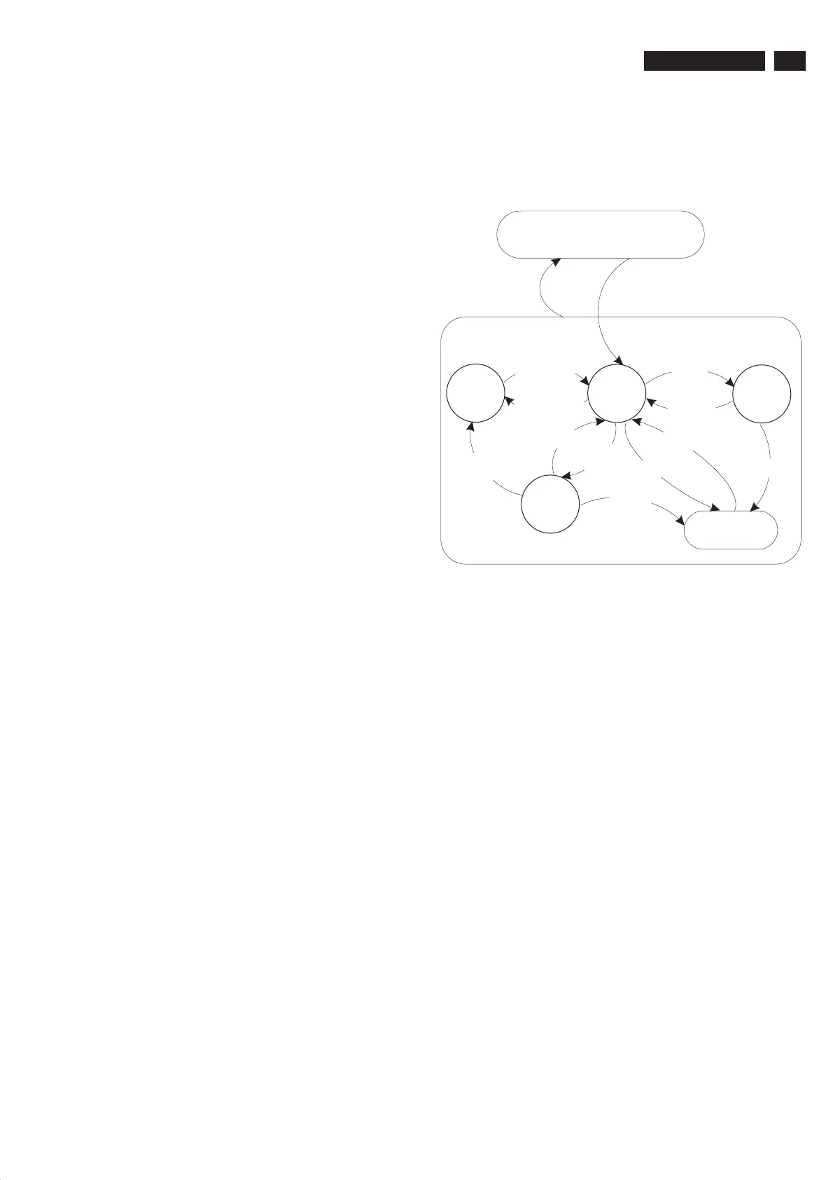
Off
Stand-by
(Off St-by)
Semi
Stand-by
Active
POD
Stand-by
Protection
- WakeUp requested
- Acquisition needed
- No data Acquisition required
and no POD present
- Tact SW pushed
- WakeUp requested
- Acquisition needed
No data Acquisition
required and
POD present
- POD Card remove
- Tact SW pushed
GoToProtection
GoToProtection
WakeUp
requested
GoToProtection
- St-by requested
- Tact SW pushed
WakeUp
requested
Fig. 5-1 Transition diagram
5.4 ComPair
5.4.1 Introduction
ComPair (Computer Aided Repair) is a service tool for Philips
Consumer Electronics products. ComPair is a further
development on the European DST (service remote control),
which allows faster and more accurate diagnostics. ComPair
has three big advantages:
ComPair helps you to quickly get an understanding on how
to repair the chassis in a short time by guiding you
systematically through the repair procedures.
ComPair allows very detailed diagnostics (on I C level) and
is therefore capable of accurately indicating problem areas.
You do not have to know anything aboutICcommands
yourself because ComPair takes care of this.
ComPair speeds up the repair time since it can
automatically communicate with the chassis (when the
microprocessor is working) and all repair information is
directly available. When ComPair is installed together with
the Force/SearchMan electronic manual of the defective
chassis, schematics and PWBs are only a mouse click away.
5.4.2 Specifications
ComPair consists of a Windows based fault finding program
and an interface box between PC and the (defective) product.
The ComPair interface box is connected to the PC via a serial
(or RS-232) cable.
For this chassis, the ComPair interface box and the TV
communicate via a bi-directional service cable via the service
connector(s).
Automatic (by communication with the television): ComPair
can automatically read out the contents of the entire error
buffer. Diagnosis is done on I C/UART level. ComPair can
·
·
·
2
2
2
·
www.freeservicemanuals.info