70
TPE1.0U LA
8. Alignments
8. Alignments
Index of this chapter:
8.1 Electrical Instructions
8.2 Software Updrade With Portable Memory
&Serial NO. Definition
8.1 Electrical Instructions&Serial NO. Definition
1. General points
1.1 During the test and measuring, supply a distortion free AC mains
voltage to the apparatus via an isolated transformer with low
internal resistance.
1.2 All measurements mentioned hereafter are carried out at a normal
mains voltage (90 - 132 VAC for NAFTA version, 195 -264 VAC for
EUROPEAN version, or 90 - 264 VAC for the model with full range
power supply, unless otherwise stated.)
1.3 All voltages are to be measurement or applied with respect to
ground,unless otherwise stated.
1.4 The test has to be done on a complete set including LCD panel in
a room with temperature of 25 +/- 5 degree C.
1.5 All values mentioned in these test instruction are only applicable of
a well aligned apparatus, with correct signal.
1.6 The letters symbols (B) and (S) placed behind the test instruction
denotes
(B): carried out 100% inspection at assembly line
(S): carried out test by sampling
1.7 The white balance (color temperature), has to be tested in subdued
lighted room.
1.8 Repetitive power on/off cycle are allowed except it should be
avoided within 6 sec.
2. Input and output signal
2.1 Signal definition
2.1.1 TV Signal type
RF Signal : Aerial input / 10mV(80dBuV)
Video signal : Video (RCA jack, CVBS input) / 1Vpp (300mV-sync,
700mV-video.)
S video input / 1VppY-signal, 300mVpp C-signal
COMP Video (RCA jack , YPbPr input) / 1Vpp Y
signal , 350mVpp Pb , Pr signal
HDMI: Digital interface with 4 channels TMDS signal
Audio signal : Audio (1) R/L( RCA jack ) for AV IN1 (share with
CVBS Video1 and COMP Video1 or HDMI by
menu setting).
Level: - Nominal : 0.5 V rms.
- Maximum : 1.5 V rms.
- Impedance > 10 k W
.
Audio (2) R/L( RCA jack ) for AV IN2 (share with
CVBS Video2 and COMP Video2).
Level: - Nominal : 0.5 V rms.
- Maximum : 1.5 V rms.
- Impedance > 10 kW.
Audio (3) R/L ( RCA jack )for AV IN3 (share with
CVBS Video3 and S-Video).
Level: - Nominal : 0.5 V rms.
- Maximum : 1.5 V rms.
- Impedance > 10 k W.
Audio (4) R/L( RCA jack ) for Side AV (share with
CVBS Video4 and S-Video).
Level: - Nominal : 0.5 V rms.
- Maximum : 1.5 V rms.
- Impedance > 10 kW.
2.1.2 Headphone
Audio: R/L output - 10mW at 32W. 3.5mm stereo jack with switch
Impedance is between 8 and 600W.
2.1.3 SPDIF Output (Sony Philips Digital Interface Format)
Level: - +/-0.5V square wave
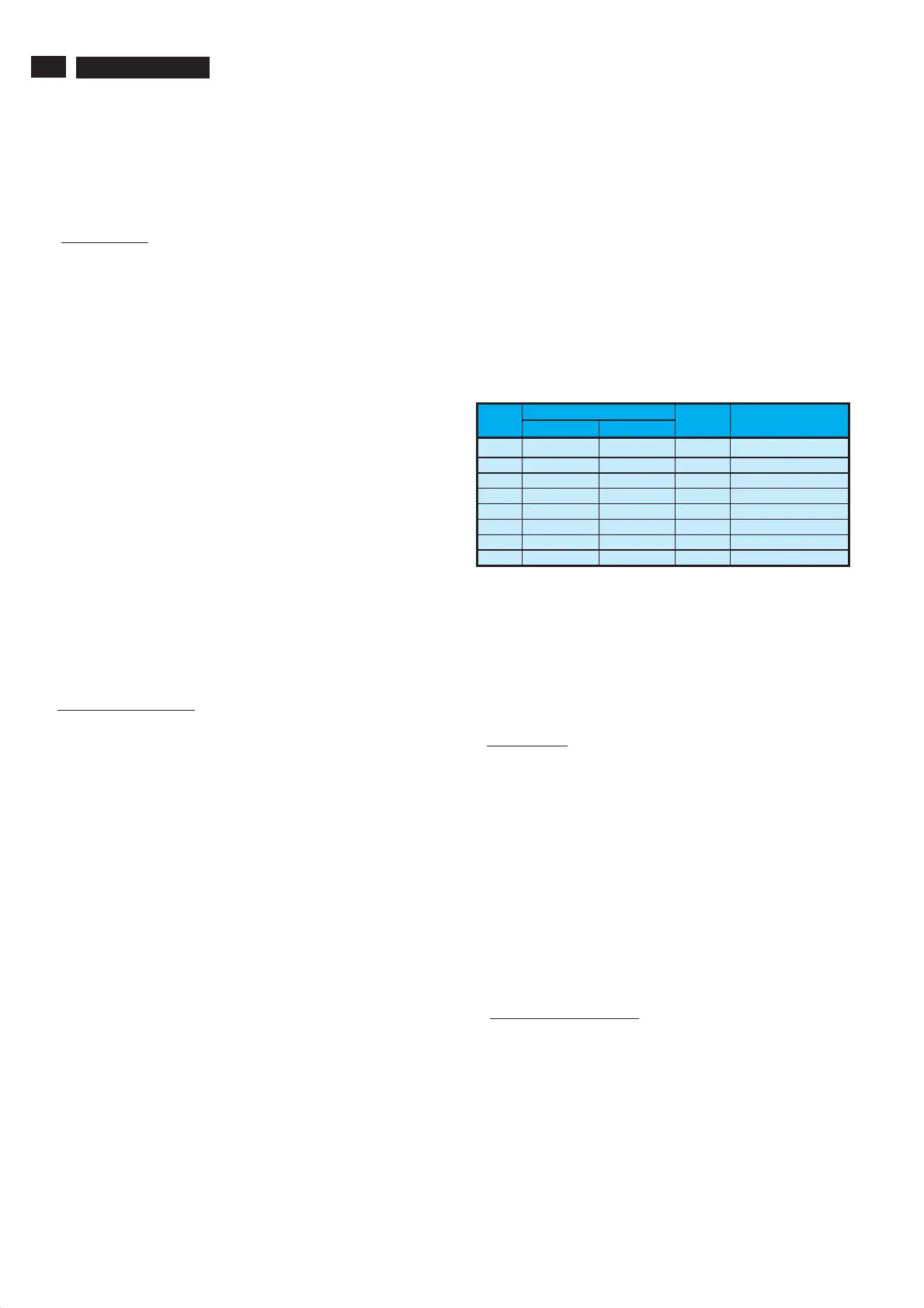
2.3 TV input signal Channel and pattern for NAFTA model (Table1)
Signal Distribution Table (NTSC)
Frequency Carriers
CH
Video Sound
TV
System
Pattern
A03 61.25MHz 65.75MHz NTSC M Color Circle
A06 83.25MHz 87.75MHz NTSC M Red Raster
A09 187.25MHz 191.75MHz NTSC M Circle Pattern
A11 199.25MHz 203.75MHz NTSC M Cross Hatch
A13 211.25MHz 215.75MHz NTSC M Two White Window
A52 699.25MHz 703.75MHz NTSC M Color Bar
A69 801.25MHz 805.75MHz NTSC M 100% White
C70 499.25MHz 503.75MHz NTSC M Checkerboard
Table 1
2.4 HD input mode
2.4.1 HD detail timing
For QuantumData setting with Q801GD or 802G in
YpbPr mode(Table 2)
3. Power supply
3.1 Setup the AC Input at 110VAC, and power board provide two DC
Output
1. The DC output voltage is 24V ± 0.5V DC for Inverter and Scalar
board . Measure between pin3 (F026, +24V) and pin7 (F030,
GND) at item 1089 of power board with 0.1A load. Measure
between pin1 (F034, +24V) and pin8 (F039, GND) at item 1088
of power board with 4A load.
2. The DC output voltage is 16V ± 1 V DC for Scalar and Audio
board. Measure between pin2 (F025, +16V) and pin7 (F030,
GND) at item 1089 of power board with 2A load.
3. The DC voltage is 400V +/- 10V in power board. Measure
between test point F004 and ground pin of item 2060 (120uF,
450V) of power board.
3.2 No adjustment is needed.
4. IF PLL Offset Adjustment
A) EQUIPMENT SETUP : Fluke 54200
B) INPUT REQUIREMENTS
4.1 Input signal : M-NTSC, RF(203.25MHz, 70dBuV)
4.2 Input injection point : Tuner input.
C) ALIGNMENT METHOD
4.3 Alignment set-up: video pattern = crosshatch, sound = BTSC
stereo mode, without audio modulation, picture/sound ratio=7dB
www.freeservicemanuals.info