8
TPE1.0U LA
4. Mechanical Instructions
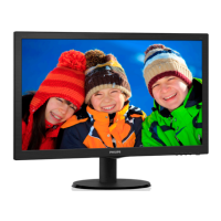
Step 4. Disconnect the USB PCB, the Side AV PCB, the KEY PCB , the
IR PCB, as Fig.14 .the Scaler PCB and power PCB
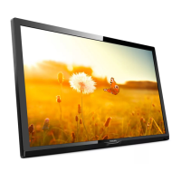
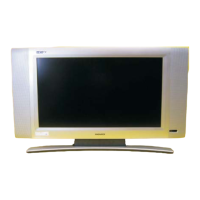
Step 5 Remove the MAIN Frame ASSY as Fig.15~Fig.17
a.
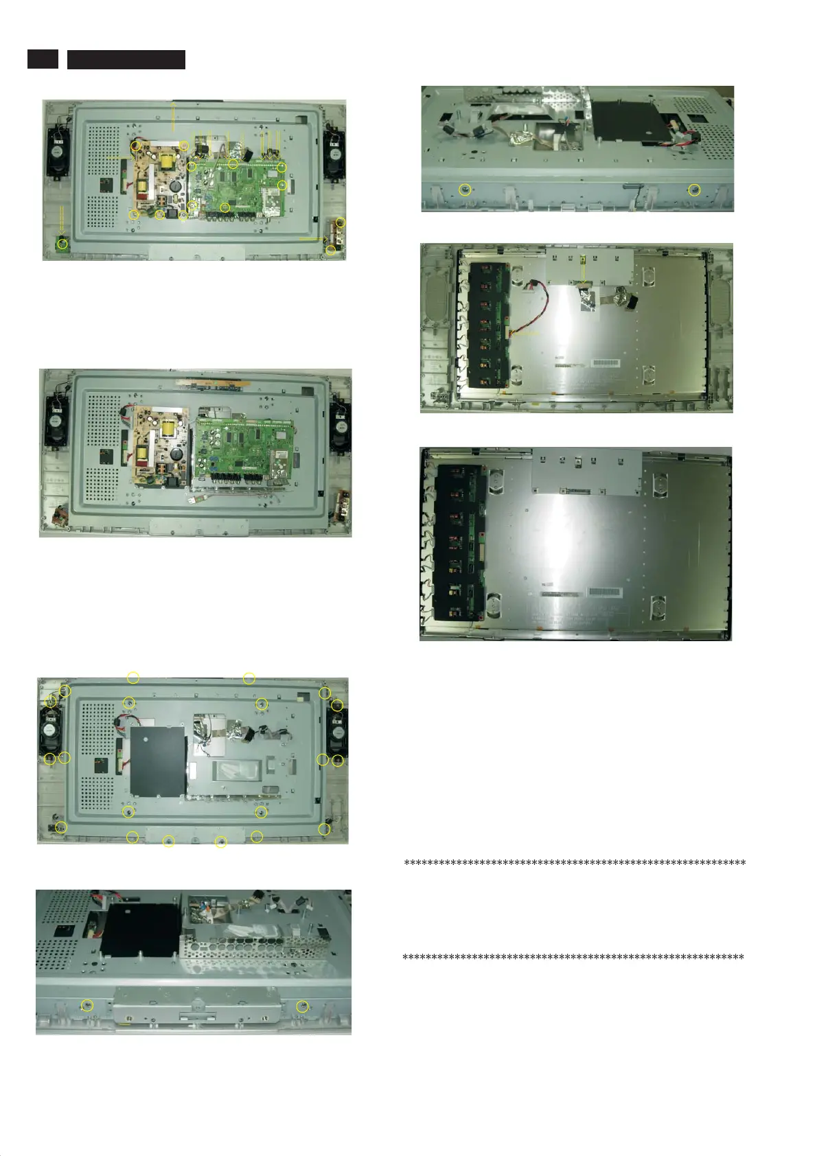
a. as Fig.18 .
b . as Fig.19 .
Remove the 24 screws as Fig.15~17 .
Step 6 Remove the Bezel assy as Fig.18~Fig.19 .
Remove the 2 connectors
Remove the Bezel assy
In warranty, it is not allowed to disassembly the LCD panel, even the
backlight unit defect.
Out of warranty, the replacment of backlight unit is a correct way
when the defect is cused by backlight (CCFL,Lamp).
Fig. 14
Fig. 15
Fig. 16
Fig. 17
Fig. 18
Fig. 19
Fig. 13
4.2 Set Re-assembly
To re-assemble the whole set, execute all processes in reverse
order.
Notes:
a. While re-assembling, make sure that all cables are placed
and connected in their original position.
b. Pay special attention not to damage the EMC foams at the
SSB shielding. Check that EMC foams are put correctly on
their places.
www.freeservicemanuals.info