Circuit Descriptions
EN 32 L11M1.1L LA7.
2011-Jun-24
back to
div. table
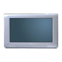
Figure 7-7 TCON key component overview
7.2 Power Supply
The Power Supply Unit (PSU) in this chassis is a buy-in and is
a black-box for Service. When defective, a new panel must be
ordered and the defective panel must be returned for repair,
unless the main fuse of the unit is broken. Always replace the
fuse with one with the correct specifications! This part is
commonly available in the regular market.
Refer to Figure 7-8
and Figure 7-9 for details
The power supply system consists of stand-by, switched and
regulated voltages. The stand-by voltage, +3V3STBY, will be
available once AC supply is provided to the system. As for the
other voltages, namely switched and regulated voltages, these
are available once the STANDBY signal is pulled “low” to allow
other supplies from the IPB to turn “on”. The switched supplies
are generated from the main +12VS supply, while the regulated
supplies are derived from the switched supplies. There are a
number of detection circuits to detect the following supplies:
+12VS, +12Vdisp and +3V3_SW. The +12VS is the main
supply voltage from the IPB that enables the switched voltages
to be generated. The +12Vdisp is the supply to the display
timing controller, while the +3V3_SW is powering the
microprocessor and its flash memory.
The mains power supply unit distribute the following voltages to
the TV system: +3V3STBY, 12VS, +24Vaudio, and +24Vpanel
for panel with inverter (or) high voltage (HV) for inverterless
panel. Requirement of the High Voltage depend on the
specification of the LCD panel.
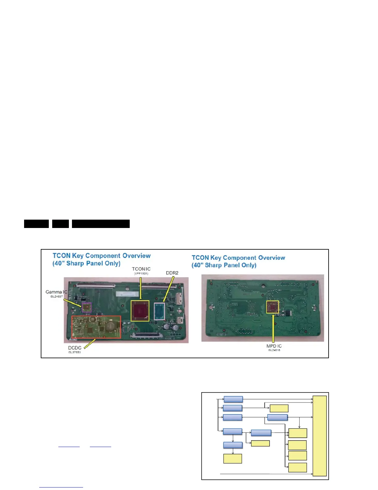
Figure 7-8 Power distribution overview
Figure 7-9 Power timing overview