Alignments
EN 26 L11M1.1L LA6.
2011-Jun-24
back to
div. table
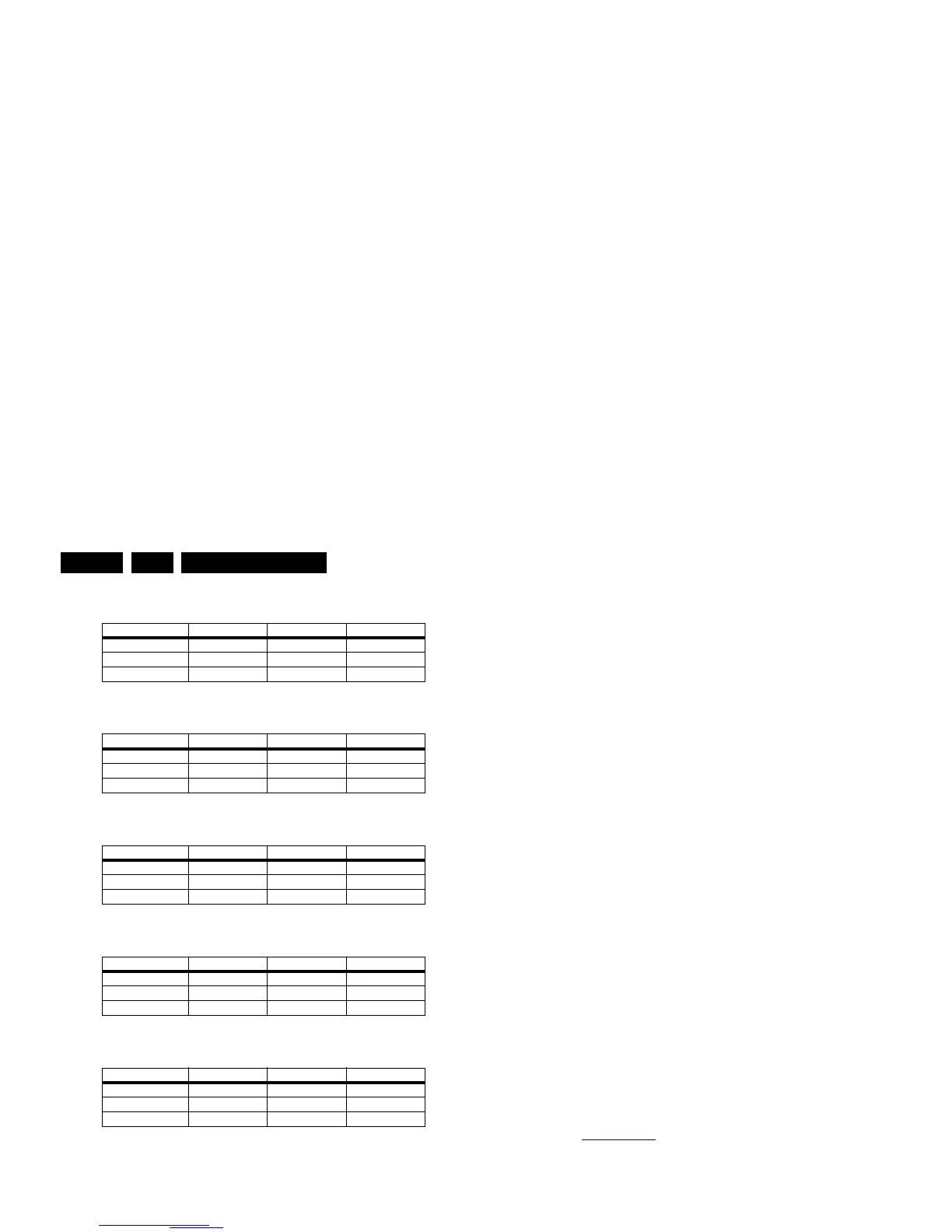
Table 6-2 Tint settings 32" Thriller HD (xxPFL3406D/xx)
Table 6-3 Tint settings 32" Thriller FHD (xxPFL3606D/xx)
Table 6-4 Tint settings 40" Thriller FHD (xxPFL3606D/xx)
Table 6-5 Tint settings 32" Berlinale FHD (xxPFL5606D/xx)
Table 6-6 Tint settings 40" Berlinale FHD (xxPFL5606D/xx)
6.4 ADC gain adjustment
Use a Quantum Data Patters Generator 802BT and apply a
“PgcWrgb” image (“dot, cross and color bar mix pattern”)
according to Figure 6-1
.
Figure 6-1 “PgcWrgb” pattern
6.4.1 YPbPr
Following instructions result in correct alignment of ADC gain,
offset and phase, related to YPbPr input signal. Apply a signal
of format “1080i25”.
• Apply following signals to the YPbPr input connectors:
– Pr signal of 0.7 Vp-p
1
/ 75 ohm to the red cinch
connector.
– Y signal of 0.7 Vb-p
2
/ 75 ohm with a sync pulse of 0.3
Vp-p
1
to the green cinch connector.
– Pb signal of 0.7 Vb-p
1
/ 75 ohm to the blue cinch
connector.
• Select the input source to YPbPr input.
• In SAM, initiate the “Auto ADC” calibration command.
Upon appearance of the “Auto ADC Completed” message, the
alignment is completed.
Notes:
1. Peak-to-Peak
2. Black-to-Peak.
6.4.2 PC VGA
Following instructions result in correct alignment of ADC gain,
offset and phase, related to PC VGA input signal. Apply a
signal of format “DMT1060”.
• Apply following signals to the PC VGA input connector:
– Red signal of 0.7 Vp-p
1
/ 75 ohm.
– Green signal of 0.7 Vp-p
1
/ 75 ohm.
– Blue signal of 0.7 Vp-p
1
/ 75 ohm.
• Select the input source to PC VGA input.
• In SAM, initiate the “Auto ADC” calibration command.
Upon appearance of the “Auto ADC Completed” message, the
alignment is completed.
6.5 TCON Alignment (= VCOM alignment)
New requirement for “TCON on SSB” project:
• The purpose of VCOM alignment is to obtain an equal
voltages for both Positive and Negative LC polarity. This is
important to avoid “Flicker” and “Image Sticking”.
• The P-Gamma + VCOM calibrator IC, ISL24837 is used for
VCOM adjustment.
• The adjusted VCOM data will be stored inside on-chip
memory and will be automatically recalled during each
power-up.
ComPair (see 5.3.1 ComPair
) will foresee in a possibility to do
this alignment.
6.6 Additional TCON Board
Thriller sets (xxPFL3x06D/xx) in the 40" range have an
additional “Philips” TCON board (diagram T01). This board
should be swapped separately from the bare LCD panel.
Alignment can be done using ComPair. All other TCON boards
come with the LCD panel and should be swapped together as
one entity.
6.7 Option Settings
6.7.1 Introduction
The microprocessor communicates with a large number of I
2
C
ICs in the set. To ensure good communication and to make
digital diagnosis possible, the microprocessor has to know
which ICs to address. The presence/absence of these specific
ICs (or functions) is made known by the option codes.
Notes:
• After changing the option(s), save them with the STORE
command.
• The new option setting becomes active after the TV is
switched “off” and “on” again with the mains switch (the
EAROM is then read again).
6.7.2 How To Set Option Codes
When the NVM is replaced, all options will require resetting. To
be certain that the factory settings are reproduced exactly, you
must set all option numbers. You can find the correct option
numbers see sticker on the inside the cabinet.
Colour Temp. R G B
Cool 201 240 255
Normal 227 255 243
Warm 243 249 164
Colour Temp. R G B
Cool 246 246 248
Normal 242 240 246
Warm 255 231 155
Colour Temp. R G B
Cool 212 244 254
Normal 231 255 236
Warm 242 252 161
Colour Temp. R G B
Cool 187 255 241
Normal 211 254 217
Warm 234 254 156
Colour Temp. R G B
Cool t.b.d. t.b.d. t.b.d.
Normal t.b.d. t.b.d. t.b.d.
Warm t.b.d. t.b.d. t.b.d.