Technical Specs, Diversity, and Connections
EN 4 TPS15.3A LA2.
2015-Oct-23
back to
div.table
2-Shield Gnd H
3 - D2- Data channel j
4 - D1+ Data channel j
5-Shield Gnd H
6 - D1- Data channel j
7 - D0+ Data channel j
8-Shield Gnd H
9 - D0- Data channel j
10 - CLK+ Data channel j
11 -Shield Gnd H
12 - CLK- Data channel j
13 - Easylink/CEC Control channel jk
14 - ARC Audio Return Channel k
15 - DDC_SCL DDC clock j
16 - DDC_SDA DDC data jk
17 - Ground Gnd H
18 -+5V j
19 - HPD Hot Plug Detect j
20 - Ground Gnd H
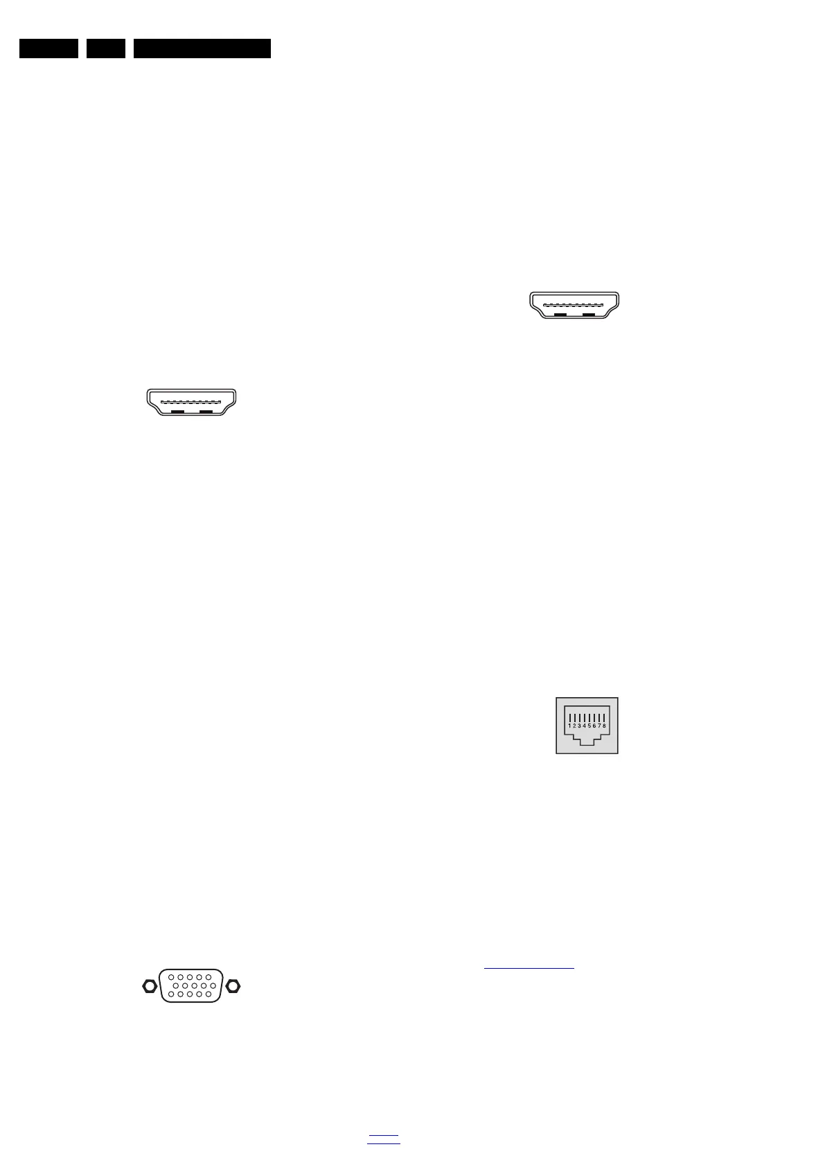
9 - HDMI 3: Digital Video - In, Digital Audio with MHL -
In/Out
Figure 2-5 HDMI (type A) connector
1 - D2+ Data channel j
2-Shield Gnd H
3 - D2- Data channel j
4 - D1+ Data channel j
5-Shield Gnd H
6 - D1- Data channel j
7 - D0+ Data channel j
8-Shield Gnd H
9 - D0- Data channel j
10 - CLK+ Data channel j
11 -Shield Gnd H
12 - CLK- Data channel j
13 - Easylink/CEC Control channel jk
14 - ARC Audio Return Channel k
15 - DDC_SCL DDC clock j
16 - DDC_SDA DDC data jk
17 - Ground Gnd H
18 -+5V j
19 - HPD Hot Plug Detect j
20 - Ground Gnd H
2.3.2 Rear Connections
10 - Cinch: Video YPbPr - In, Audio - In
Gn - Video - Y 1 V
PP
/ 75 W jq
Bu - Video - Pb 0.7 V
PP
/ 75 W jq
Rd - Video - Pr 0.7 V
PP
/ 75 W jq
Wh - Audio - L 0.5 V
RMS
/ 10 kW jq
Rd -Audio - R 0.5 V
RMS
/ 10 kW jq
11 - Audio In: PC/DVI - Left / Right,
Gn - Audio L/R in 0.5 V
RMS
/ 10 k jq
12 - PC IN:VGA
Figure 2-6 VGA connector
1 - Video Red 0.7 V
PP
/ 75 W j
2 - Video Green 0.7 V
PP
/ 75 W j
3 - Video Blue 0.7 V
PP
/ 75 W j
4-n.c.
5 - Ground Gnd H
6 - Ground Red Gnd H
7 - Ground Green Gnd H
8 - Ground Blue Gnd H
9-+5V
DC
+5 V j
10 - Ground Sync Gnd H
11 - Ground Red Gnd H
12 - DDC_SDA DDC data j
13 - H-sync 0 - 5 V j
14 - V-sync 0 - 5 V j
15 - DDC_SCL DDC clock j
13 - HDMI 1: Digital Video - In, Digital Audio with MHL -
In/Out
Figure 2-7 HDMI (type A) connector
1 - D2+ Data channel j
2 - Shield Gnd H
3 - D2- Data channel j
4 - D1+ Data channel j
5 - Shield Gnd H
6 - D1- Data channel j
7 - D0+ Data channel j
8 - Shield Gnd H
9 - D0- Data channel j
10 - CLK+ Data channel j
11 - Shield Gnd H
12 - CLK- Data channel j
13 - Easylink/CEC Control channel jk
14 - ARC Audio Return Channel k
15 - DDC_SCL DDC clock j
16 - DDC_SDA DDC data jk
17 - Ground Gnd H
18 - +5V j
19 - HPD Hot Plug Detect j
20 - Ground Gnd H
14 - RJ45: Ethernet
Figure 2-8 Ethernet connector
1 - TD+ Transmit signal k
2 - TD- Transmit signal k
3 - RD+ Receive signal j
4 - CT Centre Tap: DC level fixation
5 - CT Centre Tap: DC level fixation
6 - RD- Receive signal j
7 - GND Gnd H
8 - GND Gnd H
2.4 Chassis Overview
Refer to 9. Block Diagrams for PWB/CBA locations.
10000_017_090121.eps
090428
19
1
18 2
1
6
10
11
5
15
10000_002_090121.eps
090127
10000_017_090121.eps
090428
19
1
18 2
10000_025_090121.eps
120320
 Loading...