Mechanical Instructions
EN 18 TPL16.1E LA4.
2016-Sep-23
back to
div.table
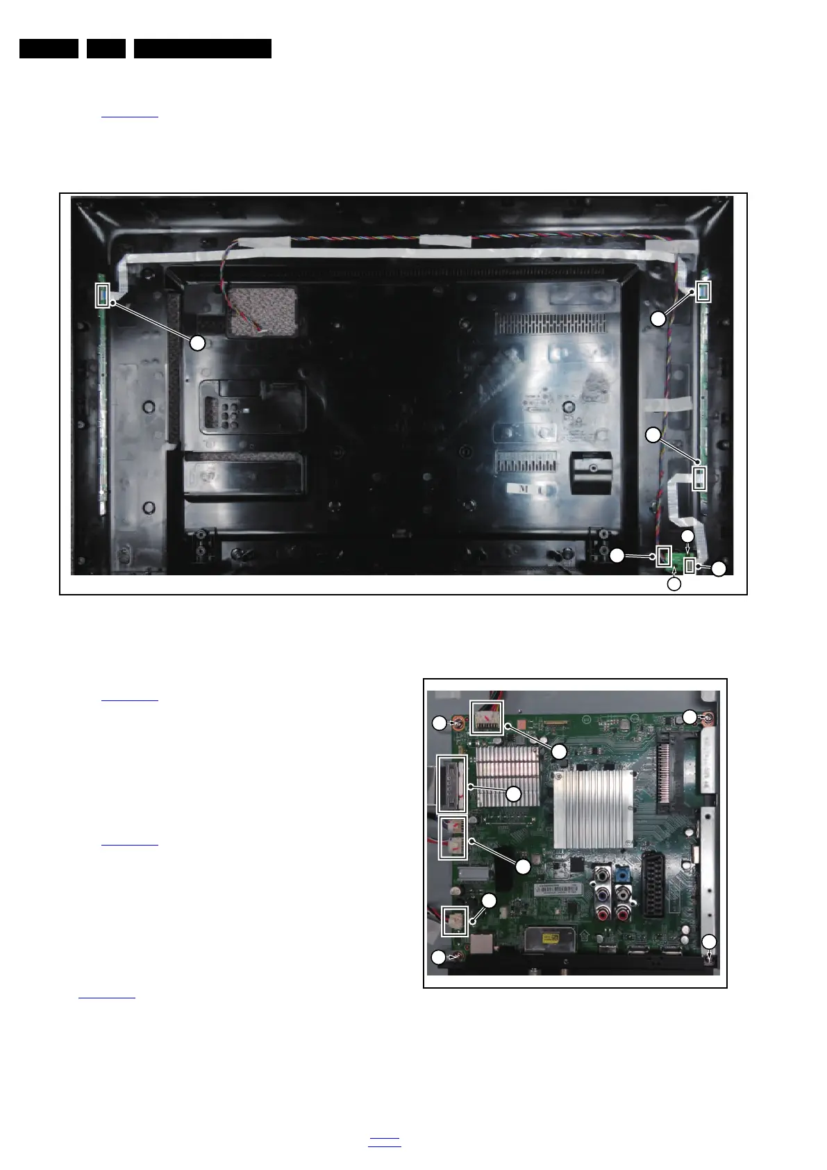
4.4.2 AmbiLight Panel
Refer to Figure 4-15
for details.
1. Gently release the clamps and unplug the two connectors
[5] that secure the ambilight panels. Release the clips from
the FFC connector that connect with the keyboard [4].
2. Lift the AmbiLight panel from the rear cover. Make sure that
wires and flat foils are not damaged while lifting the
ambilight panel from the rear cover.
Figure 4-15 Ambilight and Keyboard removal
4.4.3 Keyboard Control Unit
Refer to Figure 4-15
for details.
1. Release the connector [2] from the FRC Board, then
release the connectors [3] from the keyboard control panel.
Caution: be careful, as these are very fragile connectors!
2. Remove all the fixation screws from the keyboard control
panel [1] and take it out from the Back cover.
When defective, replace the whole unit.
4.4.4 Small Signal Board (SSB)
Refer to Figure 4-16
for details.
Caution: it is mandatory to remount all different screws at their
original position during re-assembly. Failure to do so may result
in damaging the SSB.
1. Release the clips from the LVDS connector that connect
with the SSB[1].
Caution: be careful, as these are very fragile connectors!
2. Unplug all other connectors [2] .
3. Remove all the fixation screws from the SSB [3].
4. The SSB can now be shifted from side connector cover,
then lifted and taken out of the I/O bracket. Refer to
Figure 4-16
for details.
Figure 4-16 SSB removal
 Loading...