Mechanical Instructions
EN 19TPL16.1E LA 4.
2016-Sep-23
back to
div.table
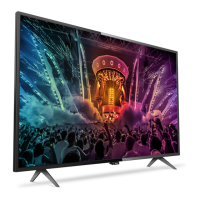
4.4.5 IR/LED Board
Refer to Figure 4-17
and Figure 4-18 for details.
1. Remove the fixation screws [1] from the stand bracket, pull
out the assy from the set. Refer to Figure 4-17
for details.
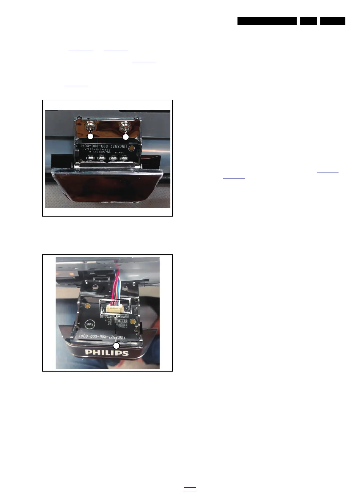
2. Carefully Releas the cover secured by clips, then unplug
the connector [2] from the IR/LED board. The IR/LED
Board can now be lifted and taken out from the cover. Refer
to Figure 4-18
for details.
Figure 4-17 IR/LED Board removal[1]
Figure 4-18 IR/LED Board removal[2]
4.4.6 Power Supply Unit (PSU)
Caution: it is mandatory to remount all different screws at their
original position during re-assembly. Failure to do so may result
in damaging the PSU.
1. Gently unplug all connectors from the PSU.
2. Remove all fixation screws from the PSU.
3. The PSU can be taken out of the set now.
4.4.7 Speakers
1. Gently release the tapes that secure the speaker cables.
2. Unplug the speaker connector from the SSB.
3. Take the speakers out.
When defective, replace the both units.
4.4.8 LCD Panel
1. Remove the SSB as described earlier.
2. Remove the PSU as described earlier.
3. Remove the keyboard control panel as described earlier.
4. Remove the stand bracket as described earlier.
5. Remove the IR/LED as described earlier.
6. Remove the fixations screws that fix the metal clamps to
the front bezel. Take out those clamps.
7. Remove all other metal parts not belonging to the panel.
8. Lift the LCD Panel from the bezel.
When defective, replace the whole unit.
4.5 Set Re-assembly
To re-assemble the whole set, execute all processes in reverse
order.
Notes:
• While re-assembling, make sure that all cables are placed
and connected in their original position. See Figure 4-1
to
Figure 4-6
.
• Pay special attention not to damage the EMC foams on the
SSB shields. Ensure that EMC foams are mounted
correctly.
 Loading...