Gantry
3-20 CardioMD Service Manual 1MAN0158-H11 04-2005 CSIP Level 1
3.2.6 Connections, Series I and II systems
3.2.6.1 Side Panel
On Series I and II CardioMD systems, all connections are routed via the side panel, with the
exception of mains power. Power is applied directly to the mains input located on the power
supply at the rear side of the table console. The side panel is also used to connect the acquisition
PC to the gantry.
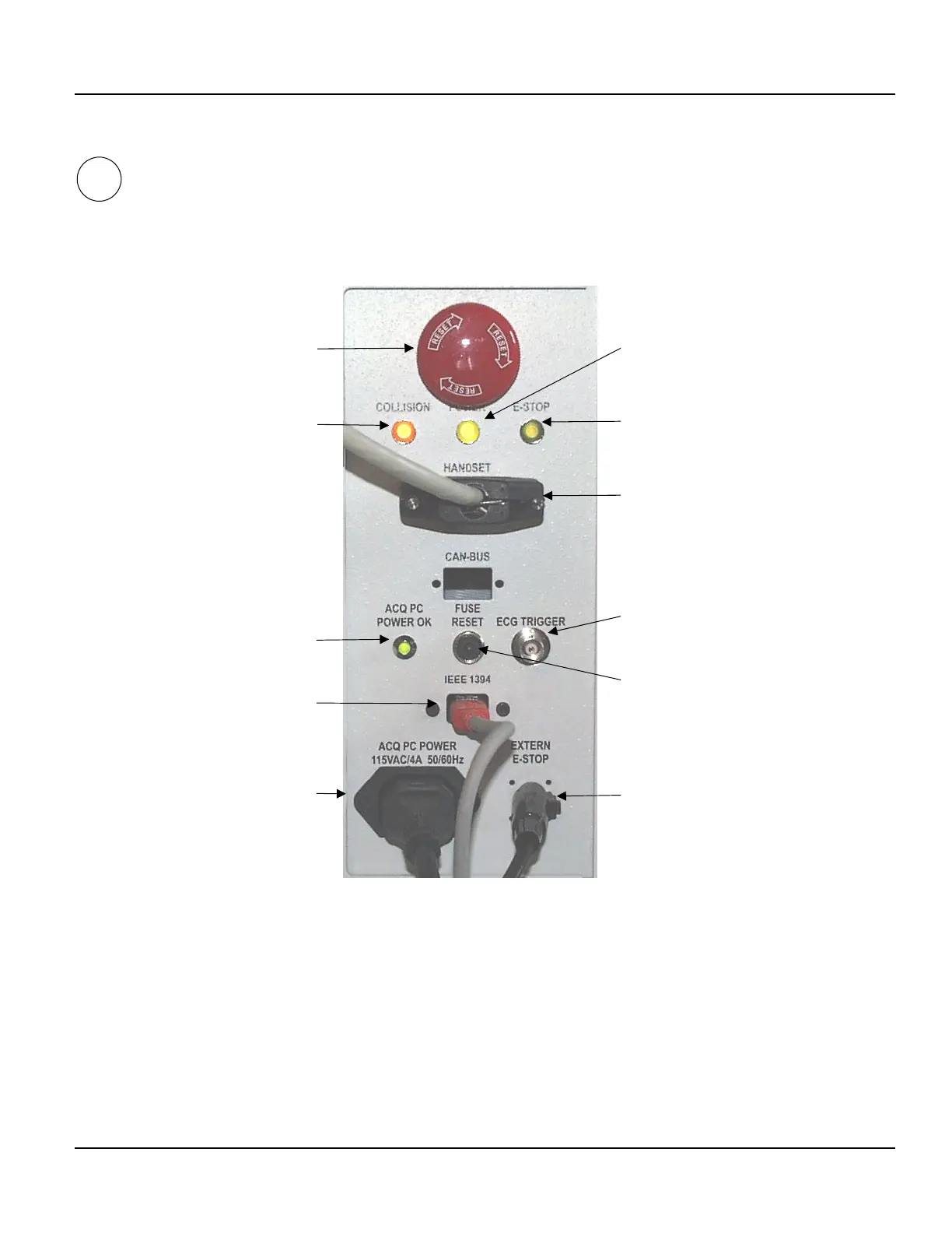
Figure 3.16 Connector panel on side of table console (CardioMD Series I and II)
Acquisition PC Power
The acquisition PC must be powered from this 115 V AC outlet. The output is protected by a
circuit breaker.
IEEE 1394 (FireWire)
The IEE 1394 FireWire connector interfaces the acquisition PC to the gantry.
Motor power
indicator
E-Stop indicator
Interface to hand
controller
Trigger input from
ECG gate
Button for resetting
acquisition PC
circuit breaker
Interface to E-Stop
located next to
acquisition PC
E-Stop
Collision indicato
Acquisition PC powe
ON indicato
IEEE 1394 FireWire
communication interface
to Acquisition PC
Acquisition PC
power connector
I, II



 To Next Page