Gantry Software Updates
7-12 CardioMD Service Manual 1MAN0158-H11 04-2005 CSIP Level 1
Procedure Details
11. When both EDC modules have been up-
dated, remount the detector top cover fol-
lowing instructions provided in Chapter 6.
Repair Procedures.
7.2.4 Collimator ID Programming
The collimator type ID is programmed into an EEPROM located on the collimator contact board.
7.2.4.1 Tools Required
• CardioMD software installation CD, part number 9CSY0906
• NULL modem serial interface cable (DB9-female to DB9-female).
• When using a laptop acquisition PC (CardioMD Series III): An USB to RS 232 adapter, part
no. 3ACQ1669.
7.2.4.2 Procedure
Before starting the collimator ID programming, check the release note on the CD-ROM. You find
the release note in the directory
Release notes. The release note may provide information that
is more recent than this manual.
Procedure Details
1. Remove the detector top cover to access
the EDC modules. See instructions in
Chapter 6 Repair Procedures.
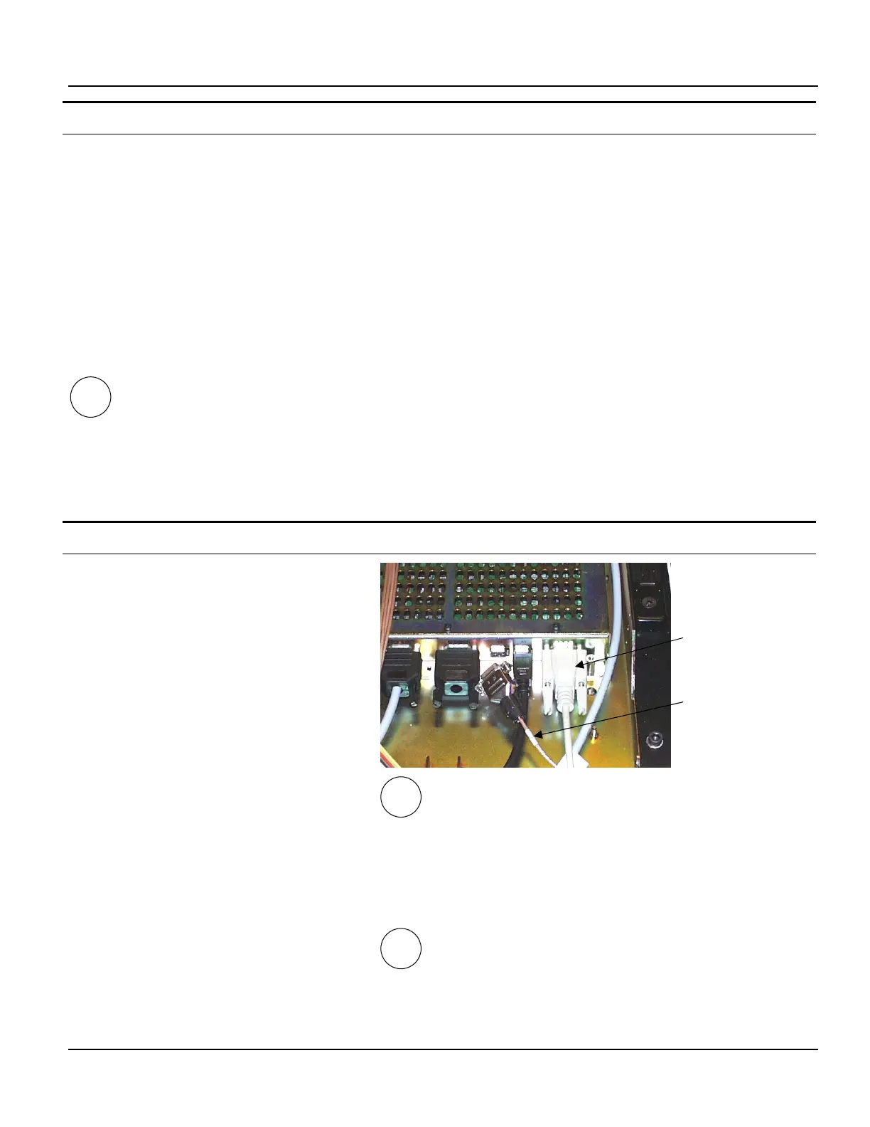
2. Remove the ECG cable from the ECG port
labeled A1 RS232.
3. Connect one end of the serial interface
cable to this port.
If you are using a laptop acquisition PC:
4. Use the USB to RS 232 adapter to connect
the opposite end of the serial interface ca-
ble to one of the acquisition PC’s USB
ports.
See section 7.2.2, page 7-2 for instructions on
determining which COM port you are using.
If you are using a tower acquisition PC:
5. Connect the opposite end of the cable to
the acquisition PC’s COM1 serial port.
III
I, II
Serial interface
cable
ECG cable
III