EN
Connect wires
Note
• Make sure that all loose leads are insulated with
electrical tape.
• Consult a professional to connect wires as instructed
below.
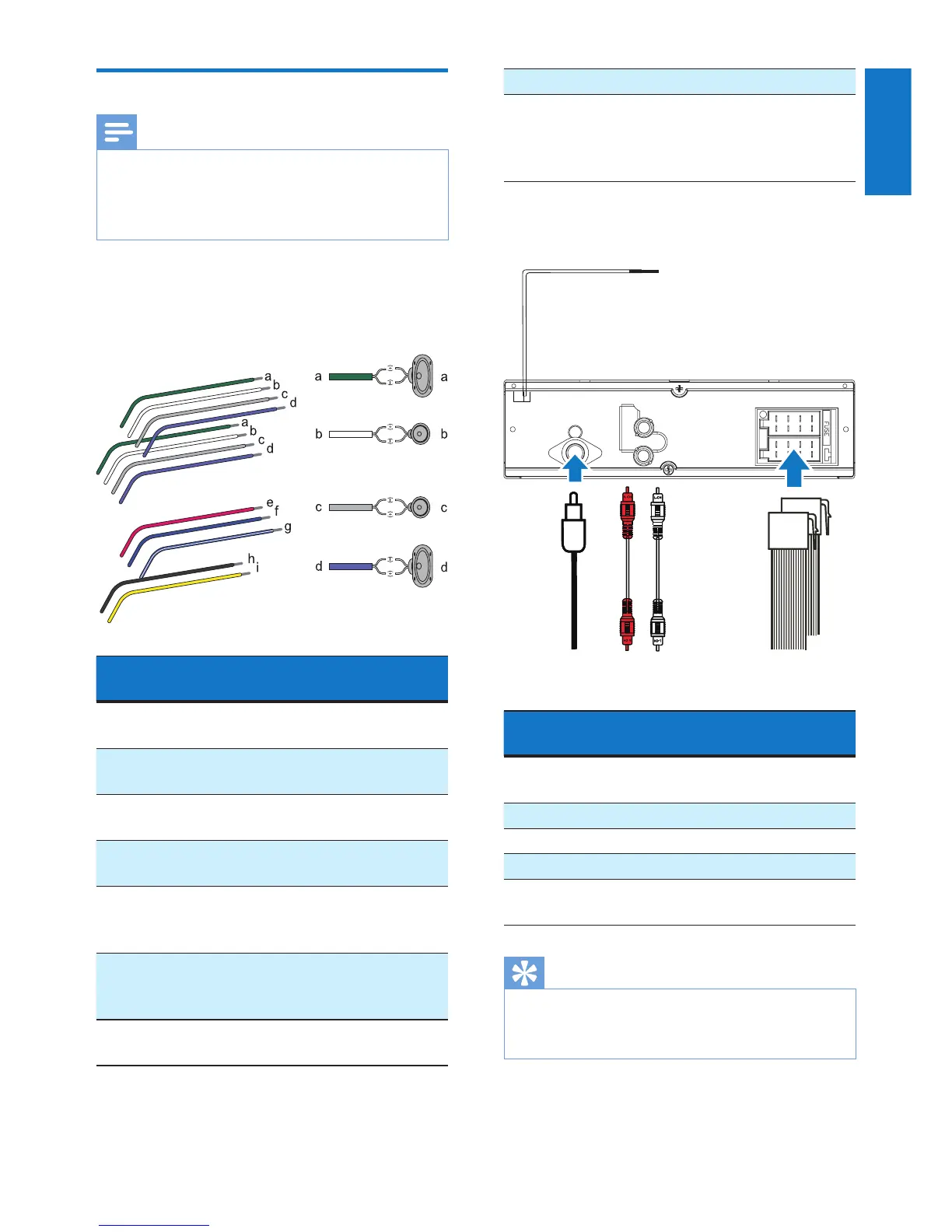
1 Check the car's wiring carefully and
connect them to the the ISO male
connectors.
ISO male
connectors
Connect to
a Green strip, black-
edged green strip
Rear left speaker
b White strip, black-
edged white strip
Front left speaker
c Gray strip, black-
edged gray strip
Front right speaker
d Purple strip, black-
edged purple strip
Rear right speaker
e Red strip Ignition key +12V
DC when ON/
ACC
f Blue strip Motor/electric
antenna relay
control lead
g White-edged blue
strip
Amplier relay
control lead
h Black strip Ground
i Yellow strip To the +12V car
battery which is
energized at all
times
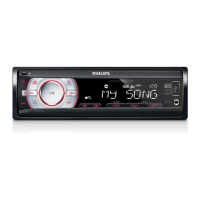
2 Connect the antenna and amplier as
illustrated, if applicable.
Sockets on rear
panel
External sockets or
connectors
1 For ISO male
connectors
As indicated above
2 REAR L Rear left speaker
3 REAR R Rear right speaker
4 ANTENNA Antenna
5 purple strip OE remote control
module
Tip
• The pin arrangement for the ISO connectors depends
on the type of your vehicle. To avoid damage to the
unit, connect properly.
REAR
L
R
abcd
e