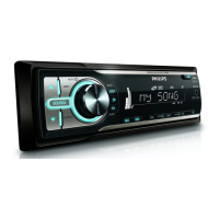
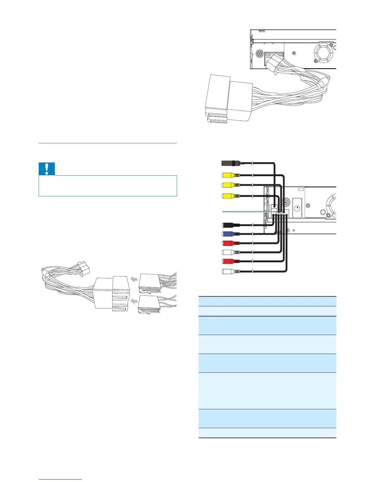
12
If necessary, connect the following:•
Connector Connect to/with
1Black cable Antenna
2Yellow
cable
Video out 1
3Yellow
cable
Video out 2
4Yellow
cable
Camera in
5 Green/
white wire
Parking (see
‘Connect parking
brake wire’ on page
14 )
6Black cable Bluetooth
microphone
7Blue cable Subwoofer
1
2
3
4
5
6
7
8
9
0
!
a Trim plate
b Standard connector
c Short mounting bracket x 2 pcs
d Rubber cushion
e Screws
- M5x16mm x 1 pc
- M4x3mm x 4 pcs
- M5x5mm x 2 pcs
- M5x5.5mm x 4 pcs
- M5x6mm x 1 pc
Connect wires: ISO connectors
Caution
Ensure that all loose leads are insulated with •
electrical tape.
1 Pull out the ISO connectors from the
car dashboard and connect them to
the bigger end of the supplied standard
connector.
2 Connect the other end of supplied
standard connector to the unit.
EN
 Loading...