11
2 Cut off the bigger end of the supplied
standard connector.
3 Check the car’s wiring carefully and
connect them to the supplied standard
connector.
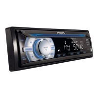
1 Green/black strip Left speaker (Rear)
2 White/black strip Left speaker (Front)
3 Gray/black strip Right speaker (Front)
4 Purple/black strip Right speaker (Rear)
eRED Ignition key +12V DC
when ON/ACC
fBLUE Motor/electric antenna
UHOD\FRQWUROOHDG$PSOLÀHU
relay control lead
gBLACK Ground
h ORANGE Illumination switch
i YELLOW To the +12V car battery
which is energized at all times
4 Connect the supplied standard connector
to the unit.
b
a
c
d
aa
b
c
d
a
b
e
f
c
d
g
h
i
b
c
d
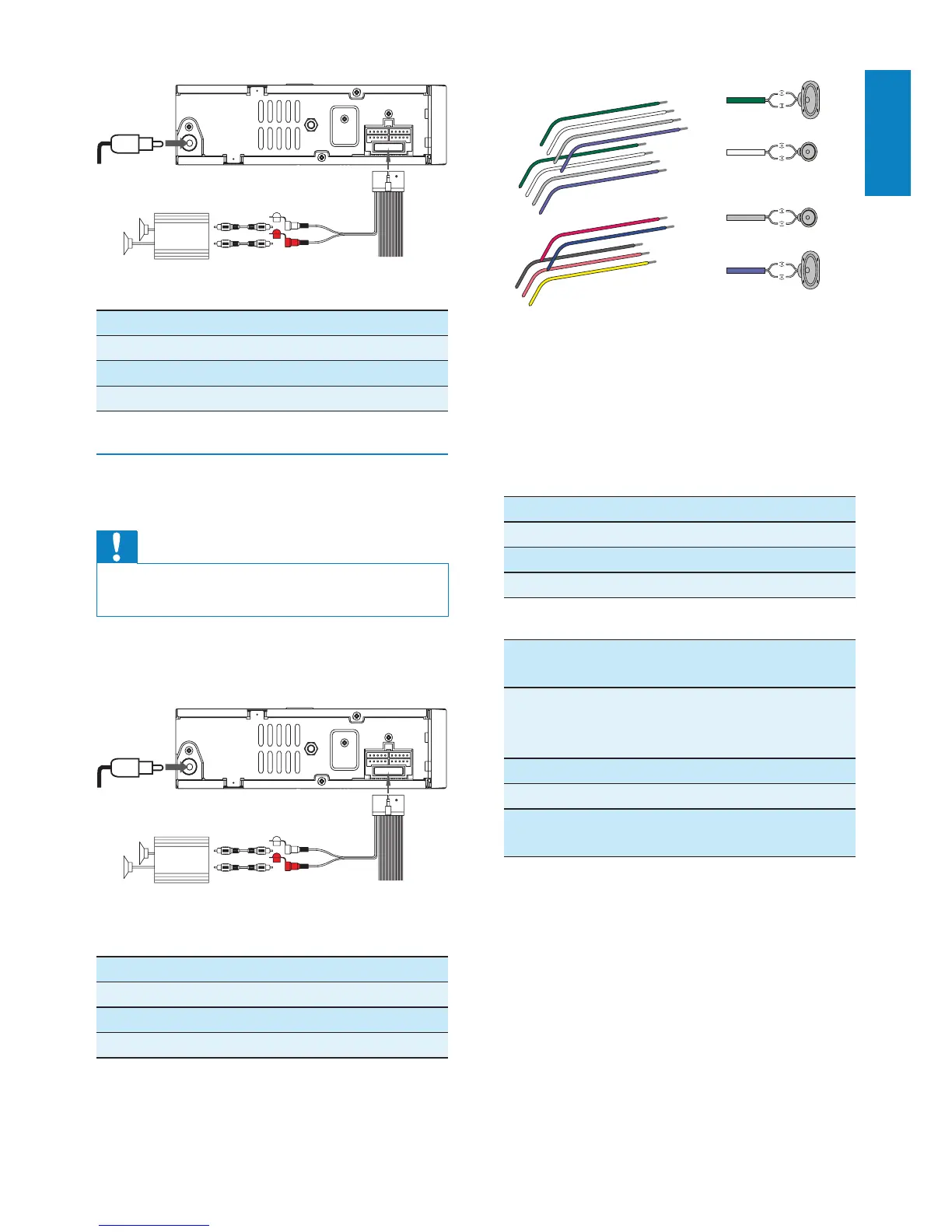
Connector Connect to
1 ANTENNA Antenna
2 REAR LINE OUT R Rear right speaker
3 REAR LINE OUT L Rear left speaker
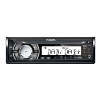
Connection: for cars without ISO
connectors
Caution
Be sure to connect the black ground (earth)
OHDGÀUVW
1 &RQQHFWWKHDQWHQQDDQGDPSOLÀHUDV
illustrated, if applicable.
Connector Connect to
1 ANTENNA Antenna
2 REAR LINE OUT R Rear right speaker
3 REAR LINE OUT L Rear left speaker
L-CHR-CH
AMP
a
c
b
L-CHR-CH
AMP
a
c
b
English
EN