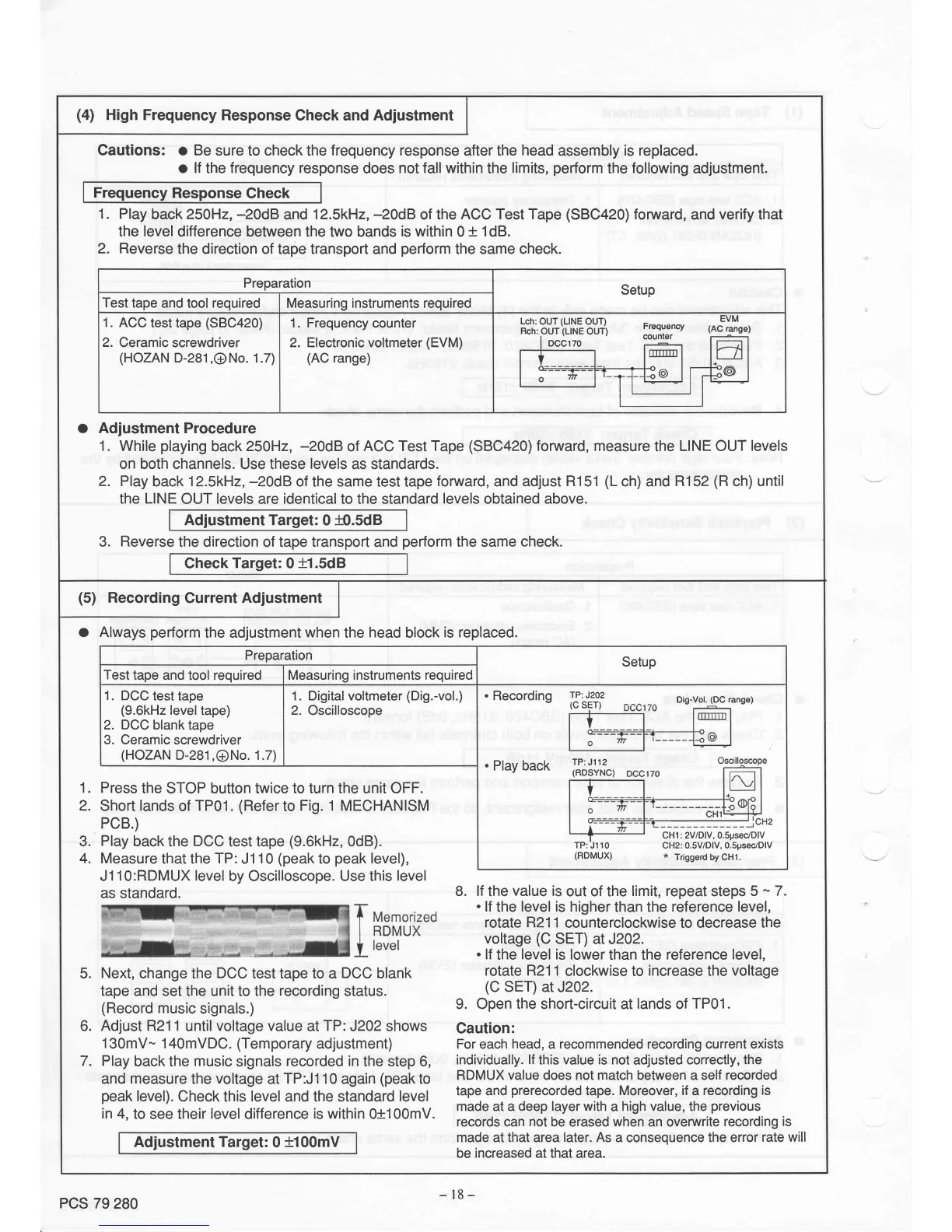
(4)
High
Frequency
Response
Check and
Adjustment
Gautions:
a
Be
sure
to
check
the
frequency response
after the
head
assembly
is replaced.
o
lÍ
the frequency response
does
not fall within
the
limits,
perform
the
Íollowing
adjustment.
Frequency
Response
Check
1. Play
back 250H2,
-20d8
and
12.5kH2,
-20dB
of the
ACC Test Tape
(SBC420)
forward,
and
verify
that
the leveldifference
between the two bands
is within
0
t 1dB.
2.
Reverse
the direction of tape transport
and
perform
the same check.
Adjustment Procedure
1. While
playing
back
250H2, -20d8
oÍ ACC
Test Tape
(SBC420)
forward, measure
the
LINE OUT
levels
on both channels. Use these
levels
as standards.
2. Play
back
12.5kH2,
-20d8 of the same test tape
foruvard,
and
adjust R151
(L
ch) and
R152
(R
ch) until
the
LINE
OUT levels are identicalto the standard
levels
obtained above.
Adjustment Target:
0
í).5d8
o
3.
Reverse
the direction of tape transport and
perform
the same
check.
Gheck
Target:
0
t1
.sdB
Preparation
Setup
Test
tape
and tool
required
Measuring instruments required
1.
ACC
test
tape
(SBC420)
Ceramic
screwdriver
(HOZAN
D-281
,G)
No. 1.7)
2.
1. Frequency
counter
2. Electronic voltmeter
(EVM)
(AC
range)
Lch:
OUT
(LINE
OUT)
Frequency
counter
Rch:
OUT
(LINE
OUT)
DCCl70
(5)
Recording
Current
Adiustment
o Always
perform
the
adjustment
when
the
head
block
is replaced.
1.
2.
3.
4.
J11O:RDMUX
level
by
Oscilloscope.
Use this
level
as standard.
5.
Next,
change the
DCC
test tape to
a
DCC
blank
tape and set the unit to the
recording
status.
(Record
music
signals.)
6.
Adjust R21 1
until
voltage
value
at
TP:
J202 shows
1
30mV^.
1
4}mVDC.
(Temporary
adjustment)
7. Play
back the
music
signals
recorded in
the
step
6,
and
measure
the
voltage
at
TP:J1 10
again
(peak
to
peak
level).
Check this
level
and the standard
level
in 4,
to see
their
level
difference
is within
0+1 00mV.
Adjustment Target:
0
t100mV
B.
ff
the
value
is
out of the
limit, repeat
steps
5
-
7.
.
lf
the
level
is higher
than the
reference level,
rotate R211
counterclockwise to decrease
the
voftage
(C
SET) at J202.
.
lf
the
level
is lower
than the
reference
level,
rotate R211
clockwise
to
increase
the
voltage
(C
SET)
aï J202.
9. Open
the
short-circuit at
lands
of
TP01.
Caution:
For
each
head,
a
recommended recording current exists
individually.
lf
this
value is
not
adjusted
correctly,
the
RDMUX
value
does not
match
between
a self
recorded
tape and
prerecorded
tape. Moreover,
if
a
recording
is
made at a
deep layer with
a
high value, the
previous
records can
not
be
erased
when
an overwrite
recording
is
made at that area later.
As
a consequence the error
rate will
be
increased
at that
area.
Preparation
Setup
Test
tape and
tool
required Measuring instruments required
1.
DCC
test
tape
(9.6kHz
level
tape)
2. DCC
blank
tape
3. Ceramic
screwdriver
(HOZAN
D-281
,ONo.
1.7)
1.
2.
Digital voltmeter
(Dig.-vol.)
Oscilloscope
.
Recording
TP:
J2o2
Dis-vot.
(DC
range)
.
Play back
TP:
J202
(c
sET)
TP: Jl12
(RDSYNC)
TP:
J110
(RDMUX)
CHl : 2V
lDlV,
O.Spsec/DlV
CH2
:
0.5V/DlV,
0.SpsedDlV
*
Triggerd
by CHl.
Press
the
STOP button twice to turn
the
unit OFF.
Short
lands
of
TP01.
(Refer
to
Fig. 1
MECHANISM
PCB.)
Play
back
the
DCC
test tape
(9.6kH2,
OdB).
Measure
that the
TP:
J110
(peak
to
peak
level),
PCS
79
280
- l8
-