Published by Philips Domestic Appliances Page 14 of 26 For internal use only
Document No. : CSW-07-081-22188
Disassembly Instruction (continue)
4.2 Reassembly Instruction
Cautions:
a. before fastening screw, relocate the screw with first thread. Once done fasten the screw.
b. Do not drop, hit or knock the ASO (for ASO version only).
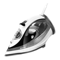
c. Ensure there is click sound after Connector to Terminal engage. Refer to wiring diagram for detail.
d. Take note of live part (red & blue wire) must apply with Heat Sink Paste after wire dressing on area as shown.
Notes: Heat Sink Paste – Dow Corning 340 Heat Sink Compound to be used.
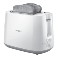
19. Remove Thermostat Bush
20. Unlock & remove CALC COLLECTOR ASSY
3 and remove COVER & SOLEPLATE ASSY 4
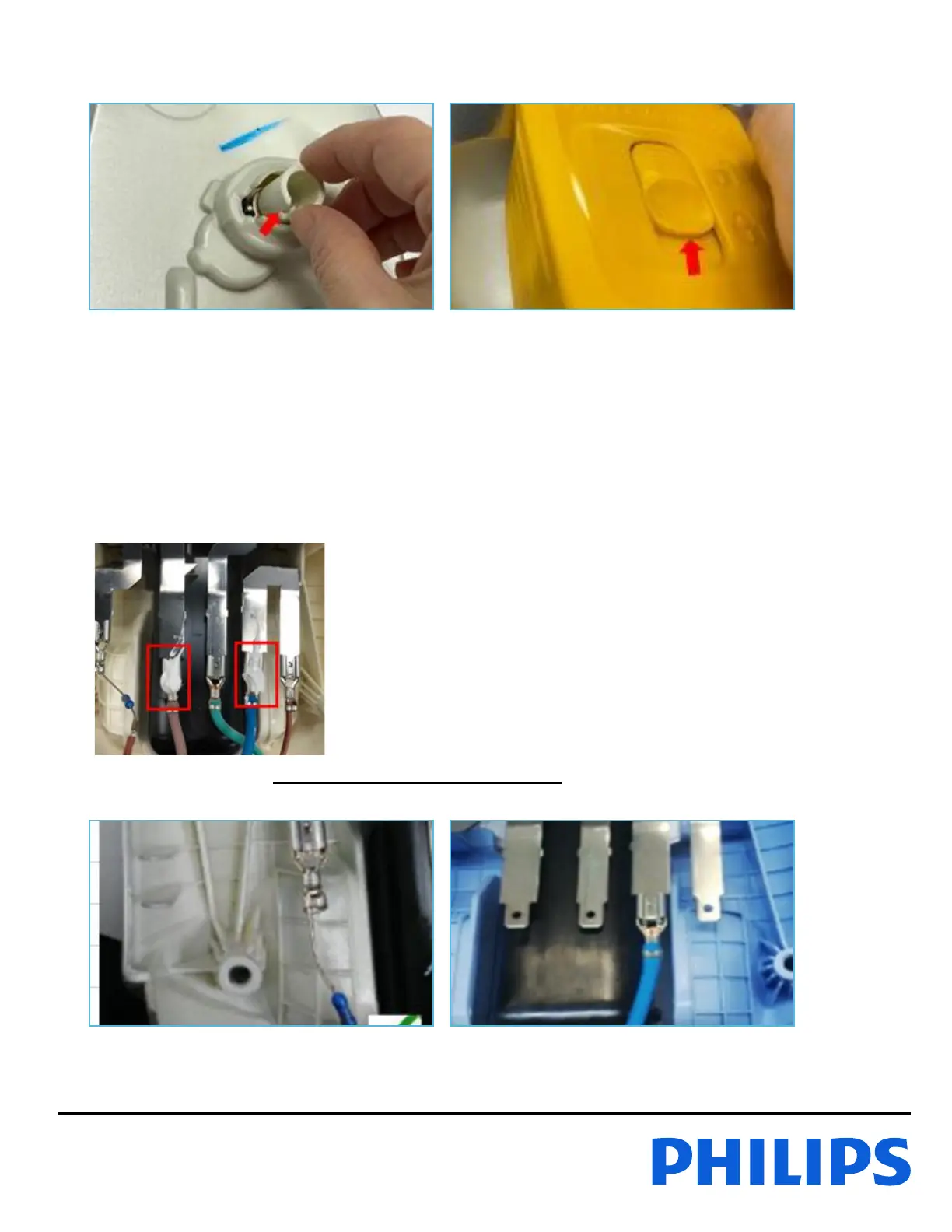
1. Connect the LAMP ASSY 9 (with resistor side)
to Frame Connector at the most left
2. Connect blue wire of MAINSCORD 6 to 'N'
Frame Connector (second from the right)