DV IN i.Link / DV jack (digital video input, IEEE 1394, Firewire): Input
for digital Camcorders or other suitable devices using this connector
(channel number 'CAM2').
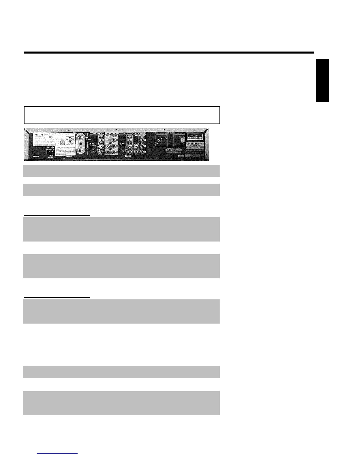
Back of the Recorder
4MAINS Power plug: Connection to the power outlet (110V/60Hz)
ANTENNA IN Antenna input: Connect your antenna or Cable TV signal here
TV OUT Antenna output: Connection to the TV
Input jacks (INEXT2)
S-VIDEO IN SVideo input: Connection for an additional device (channel number
'EXT2'). Switching between jack S-VIDEO IN and Video in is done
automatically.
Video in Video input (yellow jack): Connection for an additional device
(channel number 'EXT2')
IN L AUDIO R Analog audio input (red/white jack) underneath jack Video in .
Audio for jack Video in : Connection for an additional device (channel
number 'EXT2')
Input jacks (INEXT1)
IN AUDIO LR Analog audio input (red/white jack) next to jack IN
COMPONENT VIDEO : Connection for an additional device. Audio
input for component video (channel number 'EXT1')
IN COMPONENT
VIDEO
Component video input (red/blue/green jack): Connection for an
additional device with component video output (channel number
'EXT1')
Output jacks (OUT2)
S-VIDEO OUT SVideo output: Connection for a S-video-compatible TV
OUT VIDEO
(CVBS)
Video output (yellow jack): Connection to a TV with video input
(CVBS, Composite Video)
OUT L AUDIO R Analog audio output (red/white jack) underneath jack Video in .
Audio for jack OUT VIDEO (CVBS) : Connection for an additional
device
ENGLISH