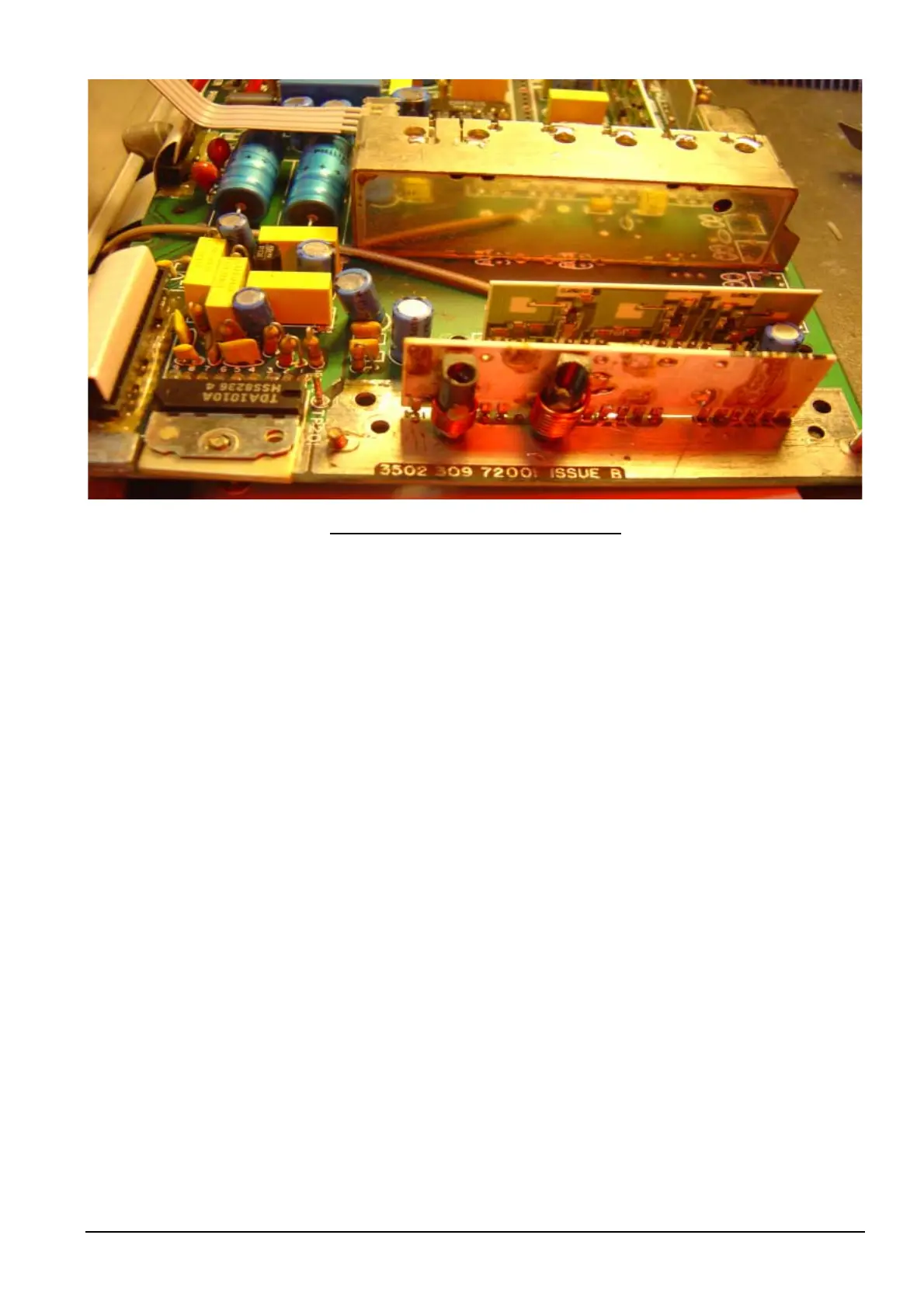
VCO PCB soldered into Receiver Board
9: Solder side to VCO module can.
10: You can now check the VCO Tuning [next section] then return back here.
11: Place VCO module over VCO PCB, which has been soldered into receiver board. Do this gently.
12: Screw VCO module to Receiver board with the two screws.
13: The tuning will have changed when you replace the VCO module can. So continue on with “VCO Tune” on
next page.
Philips FM92E Conversion to 6 Meters: Version 3.9 Page 34