Philips FM92E Conversion to 6 Meters: Version 3.9 Page 44
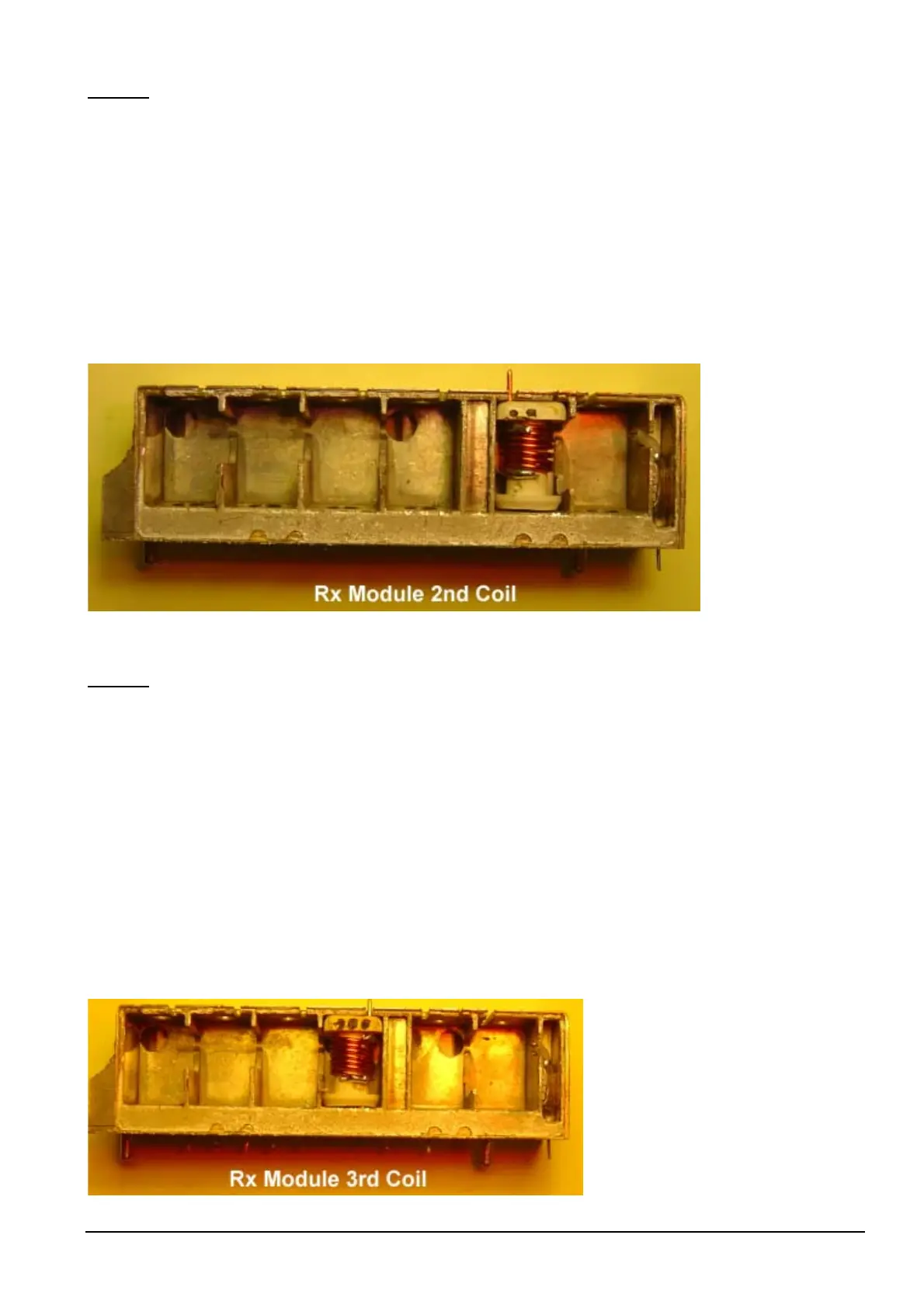
Coil # 2
• Wind coil #2 the same as coil #1, with the exceptions of:-
• The original wire length is 45mm for coil #2.
• With free end of the original wire, solder to the amplifier input on the PCB side of the Rx Module.
• 33 pF Capacitor is placed on left hand side of coil. [alongside of shield]; place capacitor in first, then coil,
then solder.
• Place into coil position #2 of Rx module.
• Solder original wire to RF amplifier input connection rear PCB side of Rx Module. Use a pair of
tweezers to help you. [see solder points on page 28]
on
Coil # 3
• Wind coil #3 the same as coil #1, with the exceptions of:-
• The original wire length is 50mm for coil #3.
• With free end of the original wire, solder to the amplifier output on the PCB side of the Rx Module.
• Push one end of the bent 0.8mm wire through a right hand hole of the square end of the coil former [for
earth connection]
• 33 pF Capacitor is placed on right hand side of coil. [alongside of shield]
• Place into coil position #3 of Rx module.
• Solder original wire to RF amplifier output connection on rear PCB side of Rx Module. Use a pair of
tweezers to help you. [see solder points on page 28]