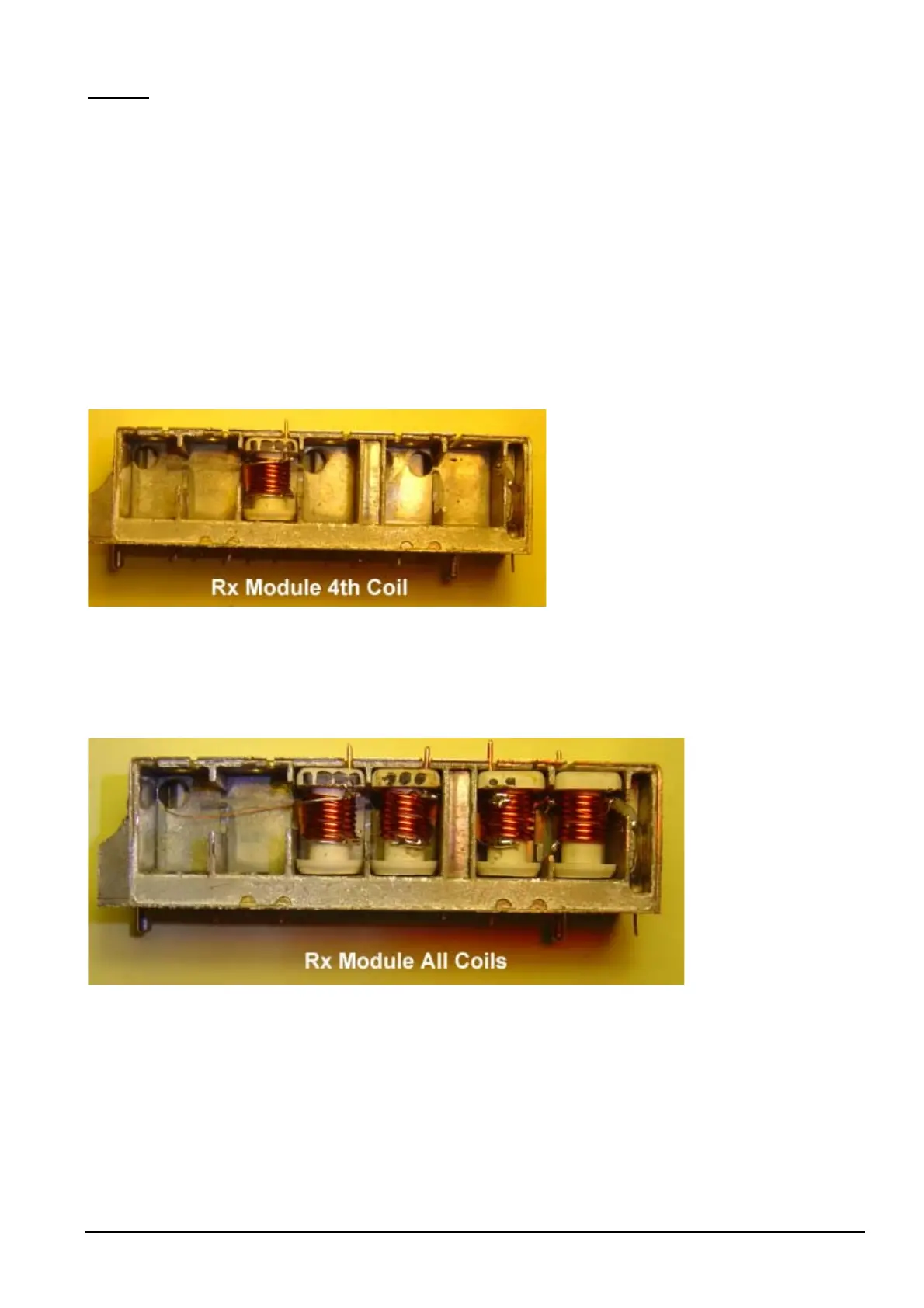
Coil # 4
• Wind coil #4 the same as coil #1, with the exceptions of:-
• The original wire length is 75mm for coil #4.
• With free end of the original wire, solder to the mixer input on the PCB side of the Rx Module..
• Push one end of the bent 0.8mm wire through a right hand hole of the square end of the coil former [for
earth connection]
• 33 pF Capacitor is placed on left hand side of coil.
• Place into coil position #4 of Rx module.
• Solder original wire to RF mixer input connection on rear PCB side of Rx Module. Use a pair of
tweezers to help you. [see solder points on page 28]
NOTE: A GDO should not be necessary if you are using 0.8mm enamelled coated wire and a NPO 33 pF
capacitor. However if you are using different dimensioned wire or a different sized capacitor, then you
should check everything with a GDO. Remember, when you place the coil into the Rx Module, the
resonant frequency of the coil changes.
Philips FM92E Conversion to 6 Meters: Version 3.9 Page 45