Aligments
EN 43S/SD/HD 3.1 PDP 8.
8.2 Adjusting procedure
42" SDv3 (SDv2)
1. Get Pattern to be Full White.
2. Adjust Vsch to 40V with VR5004.
3. Check the waveform with an Oscilloscope.
• Triggering through V-sync of LOGIC Board.
• Connect the OUT 4 Test Point at the center of Y_buffer
to other channel, and then check the first SF operating
waveform of 1TV-Field.
• Check the waveform as before by adjusting Horizontal
Division. Check the Reset waveform when the
V_TOGG Level is changed.
• Set the Vset to 10µsby adjusting VR5002.
• Set the Falling maintenance time to 30µs by adjusting
R5003.
• Change the waveform position of Oscilloscope to 3SF
and then set the Falling maintenance time to 30µsby
adjusting the VR5001. GND maintenance section
should be checked after the Vertical Division is
readjusted to '2V or 5V'.
Special Notice: When you adjust the inclination of waveform,
do check and adjustment being based on the Reset waveform
of 1st Sub-field of 1st Frame and then move to 3rd Sub-field for
adjusting.
42" HDv3
1. Get Pattern to be Full White.
2. Adjust Vsch to Clock-wise max by using VR5004 (Vsch
should be connected to "+" unit of DMM).
3. Check the waveform using Oscilloscope.
• Triggering through V_TOGG of LOGIC Board.
• Connect the OUT 4 Test Point at the center of Y_buffer
to other channel, and then check the first SF operating
waveform of 1TV-Field.
• Check the waveform as before by adjusting Horizontal
Division. Check the Reset waveform when the
V_TOGG Level is changed.
• Set the Vset to 20µs by adjusting VR5002. GND
maintenance section should be checked after the
Vertical Division is readjusted to '2V or 5V'.
• Set the Falling maintenance time to 20µs by adjusting
R5006.
• Change the waveform position of Oscilloscope to 3SF
and then set the Falling maintenance time to 10µs by
adjusting the VR5003. GND maintenance section
should be checked after the Vertical Division is
readjusted to '2V or 5V'.
Special Notice: When you adjust the inclination of waveform,
do check and adjustment being based on the Reset waveform
of 1st Sub-field of 1st Frame and then move to 3rd Sub-field for
adjusting.
S37" SDv4
1. Get Pattern to be Full White.
2. Adjust Vsch to 40V by using VR5004 (Vsch should be
connected to "+" unit of DMM). Vsch is over 95V than
Vsc_l.
3. Check the waveform using Oscilloscope.
• Triggering through V_TOGG of LOGIC Board.
• Connect the OUT 4 Test Point at the center of Y_buffer
to other channel, and then check the first SF operating
waveform of 1TV-Field.
• Check the waveform as before by adjusting Horizontal
Division. Check the Reset waveform when the
V_TOGG Level is changed.
• Set the Vset to 40µs by adjusting VR5001. GND
maintenance section should be checked after the
Vertical Division is readjusted to '2V or 5V'.
• Set the Falling maintenance time to 16µs by adjusting
R5002.
• Change the waveform voltage GND to 38V by
adjusting the VR5000.
Special Notice: When you adjust the inclination of waveform,
do check and adjustment being based on the Reset waveform
of 1st Sub-field of 1st Frame and then move to 3rd Sub-field for
adjusting.
50" HDv3
1. Get Pattern to be Full White.
2. Adjust Vsch to 25V by using VR5901_VSC_h (Vsc_h
should be connected to "+" unit of DMM).
3. Check the waveform using Oscilloscope.
• Triggering through V_TOGG of LOGIC Board.
• Connect the OUT 4 Test Point at the center of Y_buffer
to other channel, and then check the first SF operating
waveform of 1TV-Field.
• Check the waveform as before by adjusting Horizontal
Division. Check the Reset waveform when the
V_TOGG Level is changed.
• Set the Rising Ramp Flat Time to 50µs by adjusting
VR5000. GND maintenance section should be
checked after the Vertical Division is readjusted to '2V
or 5V'.
• Set the Falling maintenance time to 35µs by adjusting
R5001.
• Change the waveform position of Oscilloscope to 3SF
and then set the Falling maintenance time to 20µs by
adjusting the VR5002.
• GND maintenance section should be checked after the
Vertical Division is readjusted to '2V or 5V'.
Special Notice: When you adjust the inclination of waveform,
do check and adjustment being based on the Reset waveform
of 1st Sub-field of 1st Frame and then move to 3rd Sub-field for
adjusting.
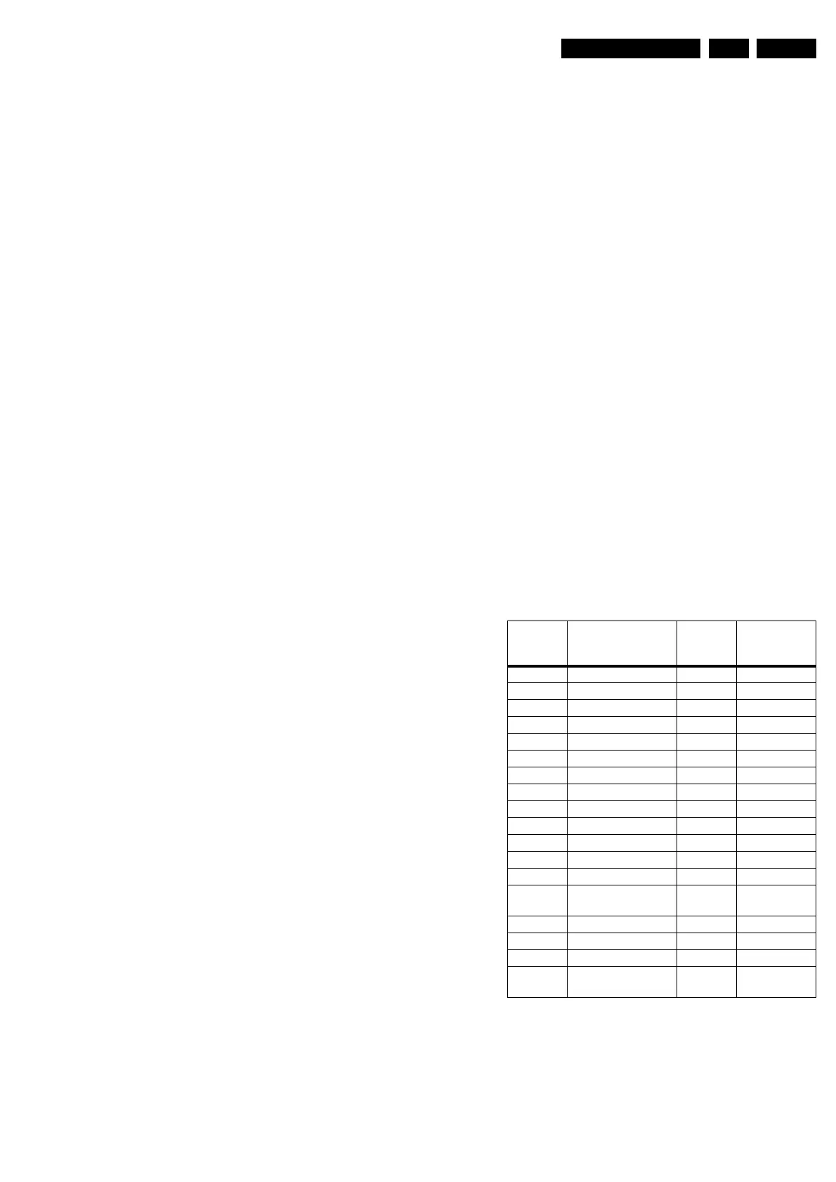
Alignment table Y PWB
Wave Form Adjusting
Location
No
Default
37SDV4 Rising_Ramp VR5001 30 µs (30 ~ 40)
Falling_Ramp_1st VR5002 16 µs (10 ~ 20)
Vsch VR5000 38V
42SDV2 Rising_Ramp (Vset) VR5003 10 µs
-Vsc 1 VR5001 20 µs
-Vsc 2 VR5002 5 µs
42SDV3 Rising_Ramp VR5002 10 µs
Falling_Ramp_1st VR5003 30 µs
Falling_Ramp_3rd VR5001 30 µs
Vsch VR5004 40V
42HDV3 Rising_Ramp VR5002 10 µs
Falling_Ramp_1st VR5003 20 µs
Falling_Ramp_3rd VR5001 10 µs
Vsch Scan high volt-
age
VR5004 40V
50HDV3 Rising_Ramp VR5000 50 µs
Falling_Ramp_1st VR5001 35 µs
Falling_Ramp_3rd VR5002 20 µs
Vsch Scan high volt-
age
VR5901 25V
 Loading...