3-2 3-3
PCS 102 489
DISMANTLING HINTS WIRING DIAGRAM
ls_l
ls_gnd
ls_r
ls_gnd
ls_c
ls_gnd
8402
8205
8002
8401
SCREW TERM
FRONT
tu_l
tu_gnd
tu_r
+12
tu_stereo
tu_clk
tu_da
tu_en
tu_rds
tu_gnd
6 XH 4 XH
6 DM
15 FFC
p_p50
p_gnd
v_sda
v_scl
v_gnd
v_sig
8 DM
HEADPHONE
+
FRONT AV
MONO II
6 DM
6 DM
5EH
5 EH
ac_h1
ac_l1
ac_gnd
ac_l2
ac_h2
SEC. TRAFO
ac1
ac2
ac3
3 EH
f1
f2
amp_prot
gnd_s
4 EH
4 EH
MAINS
relay
mfd
+v
gnd_s
2 VH 4 VH
ac_0VA
ac_120VB
ac_110VB
ac_10VB
8206
8077 8076
8009
8010
8011
8004
8012
8 DM
8405
2 DM
1401
only in
RDS version
1410
1426
1440
1441
Stby Led
1523
1521
1511
4 DM
1254
1520
1257
8 EH
1252
1251
1253
3 EH
1255
4 EH
1526
4 DM
1302
1560
6 EH
1552
0051
1064 1063
4 EH
8077
2 SDN
8076
4 SDN
1073
1074
1071
1072
5 EH
5 EH
MDM
15 FFC
4 EH
PRIM. TRAFO
1803
1802
mdm
---Left out
---Ground
---Right out
---Ground
---Center out
---Ground
---Surround left
---Surround right
---Subwoofer out
---Downmix left
---Downmix gnd
---Downmix right
---Reset
---Request
---Sda
---Scl
---Ground
--- + 6V
---Right In
---Ground
---Left In
---Ground
--- +12V
--- -12V
ssce
ssclk
ssdata
sofac scl
sofac1 sda1
sofac2 sda2
dpl clk
amp s on
amp lr on
d ground
amp prot
amp mute lr
amp mute c/s/ sub
dd reset
dd req
4 DM
1433
not in
RDS version
only in RDS
amp stby
amp pd
+5
+5D
ground d
-30
f1
f2
XH
12/JQ
XH
only/01
1305
8502
1427
2 DM
1435
2 DM
v_gnd
v_sig
1425
7 DM
8410
8408
1436
7 DM
1437
2 DM
6 EH
1515
8409
6 DM
6 EH
av_ r
av_gnd
av_ l
hp_ on
hp_gnd
hp_ r
hp_ l
8407
8 DM
ac_A
ac_fuse
-VH
-VL
ls_gnd
ls_gnd
gnd
gnd
+VL
+VH
av_ r
av_gnd
av_ l
hp_ gnd
hp_ r
hp_ l
MDI /FR975 /update 28-03-00
TUNER
4 XH
VIDEO SELECTOR
P50 Board &
8008
FR975
+12
v_gnd
subw.pre out
s_gnd
8202
1270
1272
1266
1903
8208
8207
1503
3 DM
1563
8503
c-sig
gnd
subw sig
3 EH
1402
8504
1554
5 DH
1960
5 EH
SVHS
VIDEO
SELECTOR
+12
gnd
v_sda
v_scl
v_gnd
12/JQ
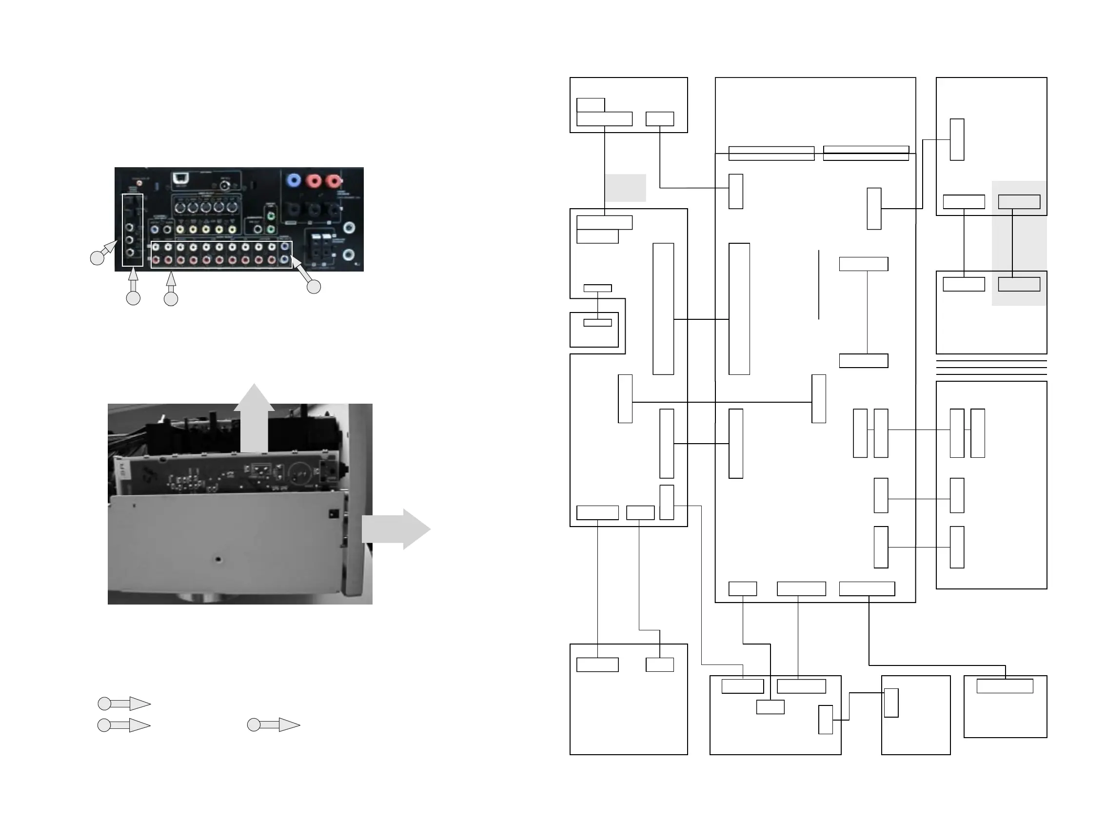
Dismantling of MDM module
1) Remove all the screws mentionned in the arial . See picture 11
picture11
2) Remove backplate a little backwards. See arrow 1 (picture 12)
3) Pull module out the set as shown in picture 12
picture12
1
3
3
2
2
6x
1
= Torx M3x6mm ( screw with big head )
Legend
2
= Torx 3x10mm
3
= Torx M3x6mm
1x
1x
4x
2
www.freeservicemanuals.info