Mechanical Instructions
EN 11FTL2.4E AA 4.
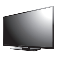
Figure 4-15 Speaker and LCD backlight cables
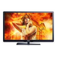
Figure 4-16 LCD panel disassembly (part 1)
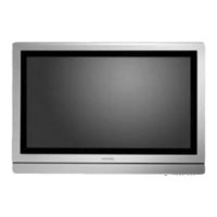
Figure 4-17 LCD panel disassembly (part 2)
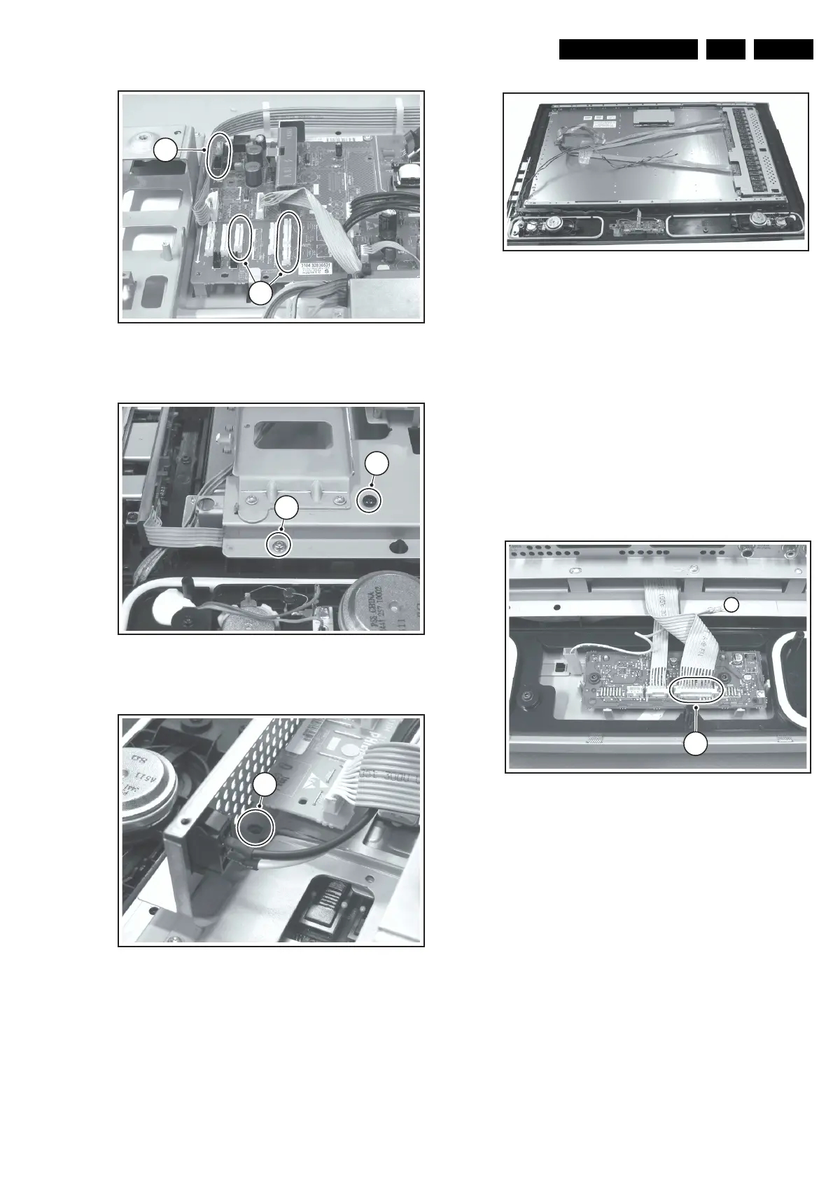
Figure 4-18 Bare LCD panel after frame removal
4.5 Set Re-assembly
To re-assemble the whole set, execute all processes in reverse
order.
Note: While re-assembling the TV, make sure that:
• All cables are placed and connected in their original
position (see figure “Chassis cable dressing” in the
beginning of this chapter and/or the “Wiring Diagram” in
chapter 6).
• LVDS connector (SSB) is secured with plastic clamp.
• The "grounding" wire between metal speaker grid and
frame [1] is reconnected.
–
Figure 4-19 Metal speaker grid grounding wire
F_15490_021.eps
240605
4
3
F_15490_019.eps
240605
6
5
F_15490_020.eps
240605
7
F_15490_022.eps
240605
F_15490_025.eps
240605
1
2