Mechanical Instructions
EN 10 FTL2.4E AA4.
4.3.11 SSB
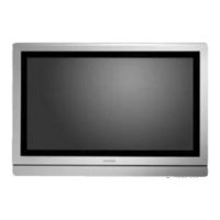
1. Remove the LVDS connector locking bracket [1][2].
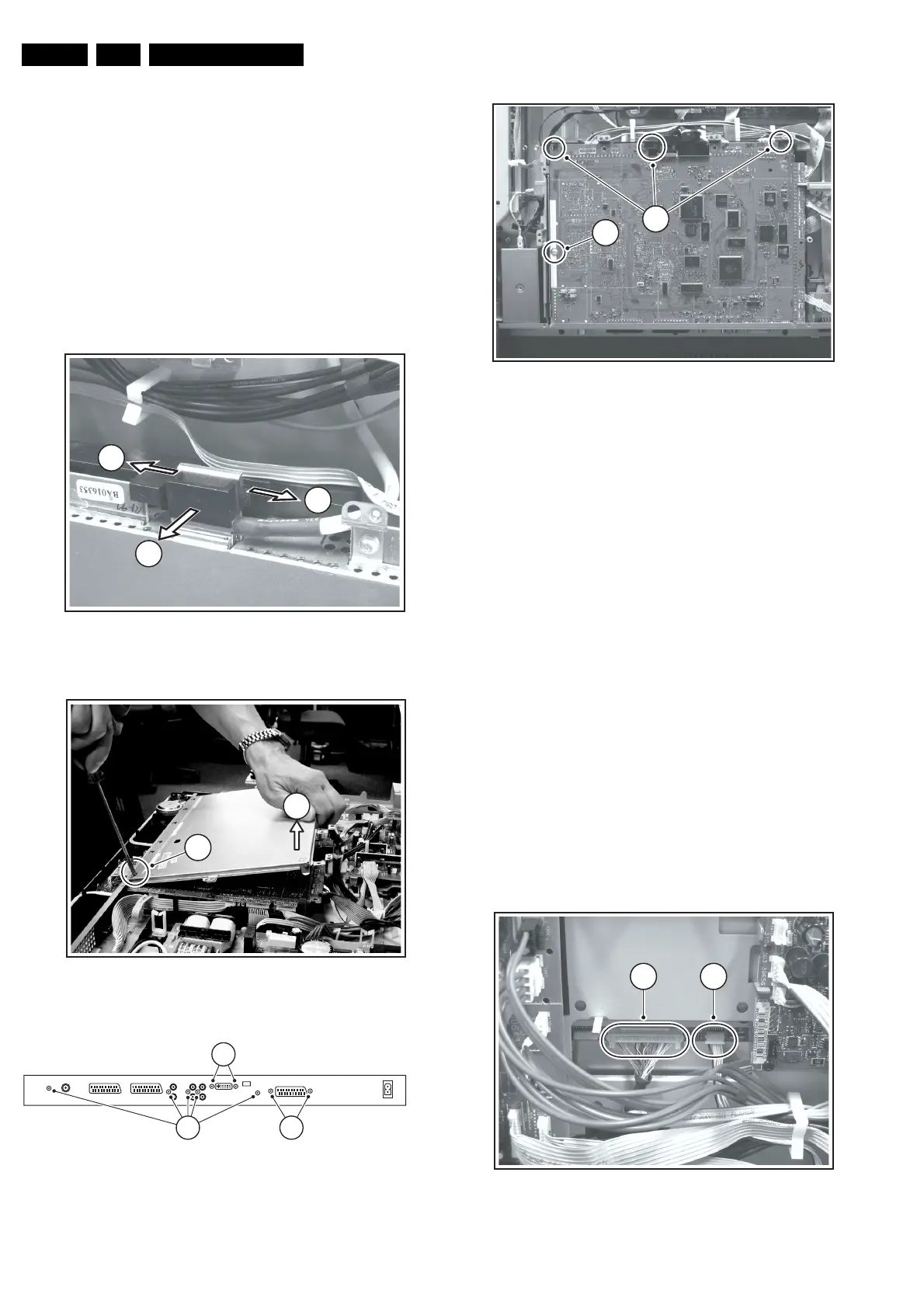
2. Remove all shielding fixing screws.
3. Slide, and lift the shielding at the top [3]. The panel hinges
at the SCART side. At the same time, use a screwdriver to
carefully prize the shielding at the bottom side [4], and
remove the shielding. The SSB is now accessible.
4. To remove the whole SSB, unscrew all connector fixing
screws from the connector plate [5][6]. Use a 5 mm socket
screwdriver to remove both DVI connector distance bolts
[6].
5. Disconnect the LVDS cable, and all other cables.
6. Remove the mounting screw [8] from the SSB.
7. Bend the brackets [9] away (may require some force), lift
the SSB, and take it out.
Figure 4-10 LVDS connector locking bracket
Figure 4-11 SSB top shielding
Figure 4-12 Connector plate
Figure 4-13 SSB brackets
4.3.12 AmbiLight Lamp Unit
The AmbiLight lamp units are located in the TV’s rear cover.
1. Remove the cable clamps.
2. Remove all mounting AmbiLight screws.
3. Slide the AmbiLight unit to the side and take out the unit.
4.4 Display (Dis)Assembly
Important: Be sure to work in a dust free environment during
the following activities. In addition, the use of (fabric) hand
gloves is advised.
1. Important: Unplug the cables [1][2] at the LCD panel. Be
careful, as the LVDS connector [1] is very fragile!
2. Unplug the backlight and loudspeaker connectors [3][4].
3. Remove all T10 screws [5] from the mounting frame.
4. Remove all mounting LCD panel screws [6]. One of them
[7] is somewhat hidden underneath the SCART panel.
The best way to remove this screw is to loosen the 3th
SCART panel first via the 2 screws at the SCART
connector (see [7] in figure “Connector plate” earlier).
5. Lift the metal frame (together with all PWBs) from the LCD
panel. During lift, free the backlight and speaker cables.
6. After removal of the frame, you can lift the LCD display
from the set.
Figure 4-14 LCD panel connectors
F_15490_017.eps
240605
1
1
2
F_15490_015.eps
230605
4
3
F_15490_026.eps
240605
75
6
F_15490_027.eps
240605
9
For
PDP
8
F_15490_018.eps
240605
1 2
Fragile !